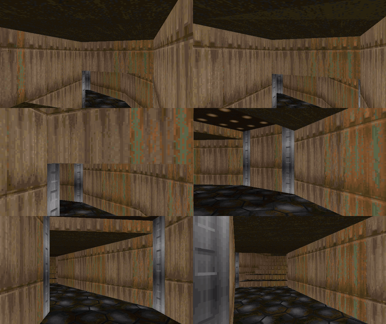
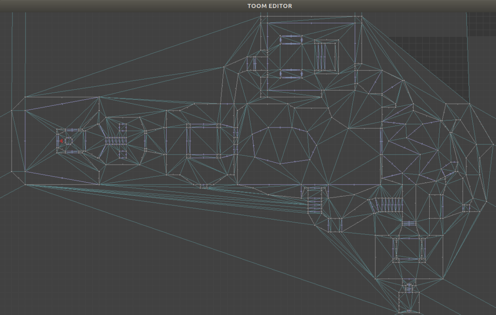
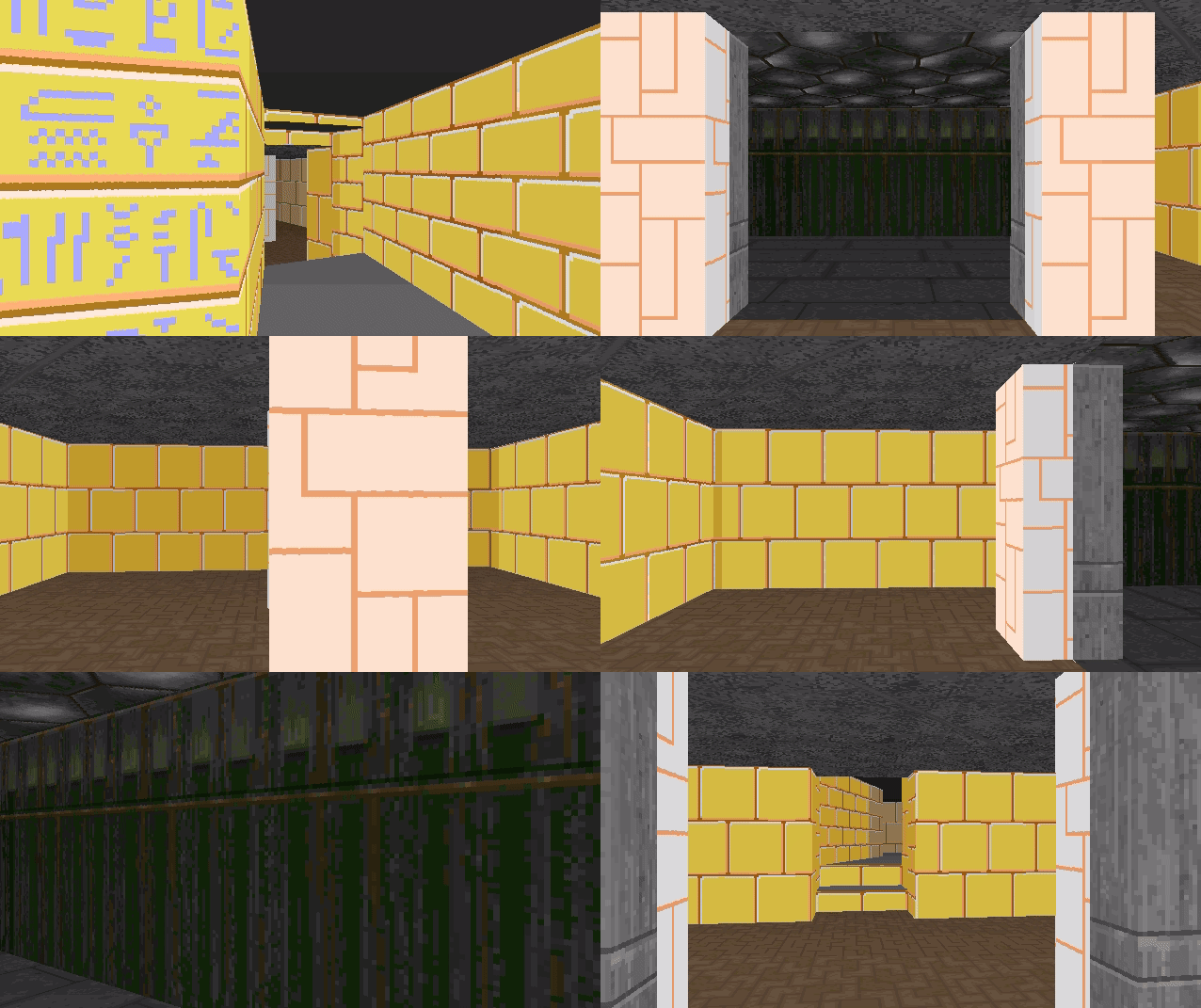
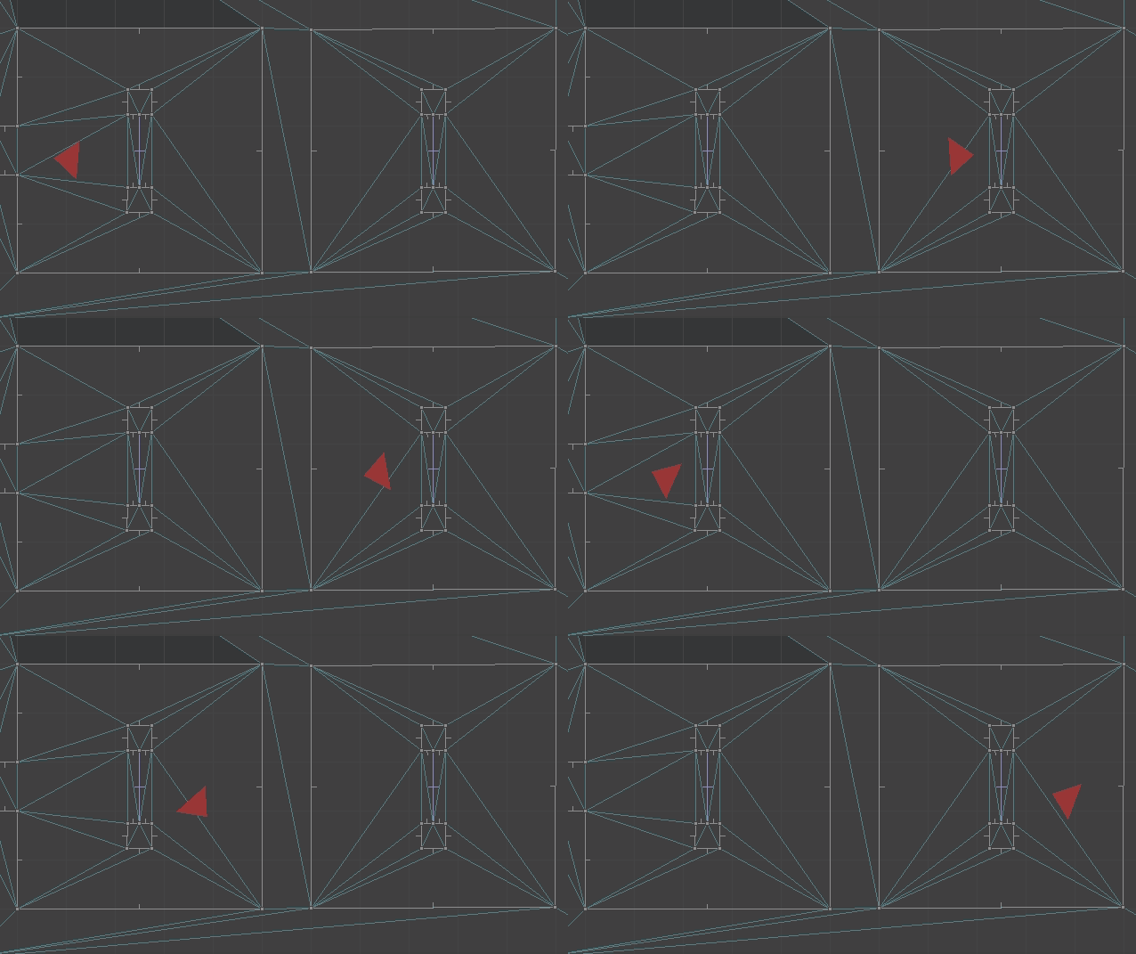
A Side Scroller Physics System

With TOOM done’, I found myself wanting to try something new. So, I started a new vscode workspace and embarked on a new side project – a 2D side scroller.

My overarching goal, once again, is to explore and take it as far as I find it interesting. That being said, I want to overcome the challenge of building a stable game with general 2D physics. By that I mean, “vectorial” physics of the sort used by Braid, with arbitrary 2D level geometry:

Braid level game view and level editor view (image from Higher-Order Fun)

One reason for this goal is that I’ve tried to noodle it out before, but was surprised to find a significant lack of resources. In fact, I had to laugh out loud when I read this excellent heavily cited blog post about 2D platformers. It covers tile-based and rastered platforms in great detail, only to leave vectorial platformers with a vague “you do it yourself” and a warning not to use a physics engine. Well, challenge accepted! Let’s get into it!

There are a few other things I want to learn from this adventure. I plan to eventually use 3D GPU-accelerated graphics. Its worth knowing how that works, and the work on TOOM convinced me that drawing with the CPU is super slow. The aesthetic I have in mind is pretty low-poly, so while I’d normally go with pixel art because that’s all I can reasonably attempt myself, I nevertheless want to give 3D a try. The other big reason to go with 3D is that I can build an animation system and animate characters once rather than 8x for the various viewing angles. I was wanting to build a skeletal animation system, but felt that 2D skeletal animation systems very easily feel flat without serious artistic effort.

The general image I have in my mind is a souls-like 2D platformer with movement and combat somewhat similar to playing Link in Super Smash, except with some additional movement mechanics like ladders and other climbable surfaces and no bubble shield. It’ll probably never be a full game but maybe I can make a proper level and boss at the end.

I’ll be using C++ and vscode for this, on Linux. I’ll try to minimize library use, but will leverage SDL2 as my platform library and probably OpenGL for 3D graphics. I love ImGui and will use that for dev UI.

What I tried first Didn’t Work

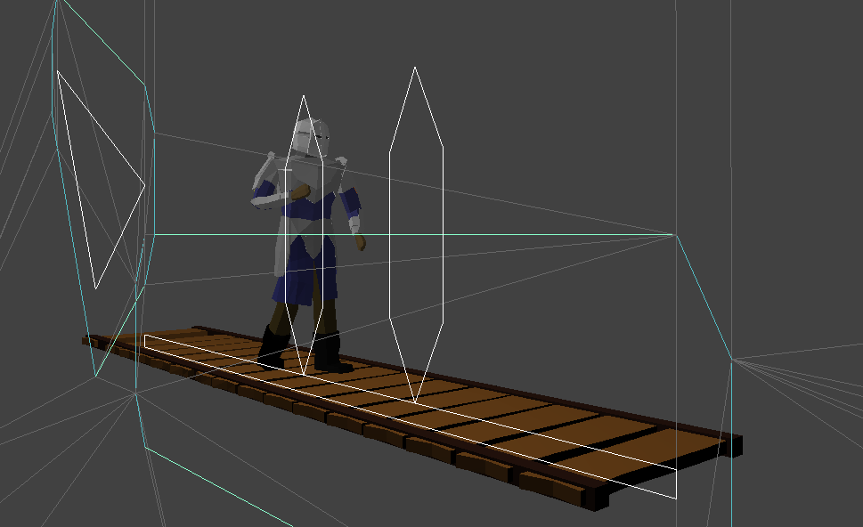
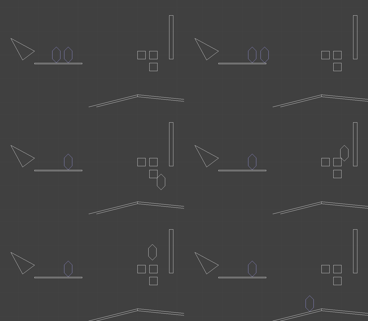
When I first started, I tried to go with an object system where the world is made of convex polygonal colliders. Seems reasonable:

The player (and one enemy) have colliders represented by these six-sided shapes. The white polygons are static geometry. So far so good.

When an entity moves, it ticks forward by \(\Delta t\). I could have done this the boring way by:

  1. Moving the entity its full distance
  2. Checking for collisions
  3. Shunting the entity out of any colliding polygons

I’ve written about why this is a bad idea. In short, this approach can cause tunneling or other weird physics effects, especially when the entity is moving fast or when there are multiple intersecting bodies.

The system I implemented sought to instead find the first collision. This is the same as taking the source polygon and sweeping it along the direction of travel and finding the longest sweep \(\delta t \in [0, \Delta t]\) that does not intersect anything:

This sweeping method is harder to formulate. We aren’t really colliding the player’s collider with each static collider. Instead, we are colliding the swept player collider with each static collider, but we still want to back out the maximum step we can take in our direction of motion. So we’re effectively sweeping the player collider along \(\Delta t \cdot \boldsymbol{v}\) and then checking for collisions, and we have to find the smallest \(\delta t\) such that the volume swept along \(\delta t \cdot \boldsymbol{v}\) does not collide.

The way I implemented that was to fall back to our trusty strategy of using the Minkowski sum. That is, we can expand the other polygon by the player’s collision volume first, and then all we have to do is check whether the line segment between the player’s starting location and that location shifted by \(\Delta t \cdot \boldsymbol{v}\) intersects with the polygon:

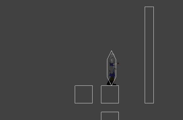
That mostly worked. It just has a lot of trouble with corner cases. For example, when the player is standing on a surface and we’re traveling along it. We don’t want floating point errors to accidentally place the player inside the supporting polygon. This was particularly problematic in the gameplay gif above, where the player ends up wedged between two squares and slides through one of them.

I had a lot of trouble with walking. I wanted the player to be able to walk across colliders along the floor without treating it like a ramp and launching off for a bit:

This means we have to do some hacky checks to figure out when we’re walking along a polygon and reach its end, and may need to transition to walking along a new polygon. I tried getting this all to work reliably, and got pretty far, but ultimately the number of hacks I had to add made the system untenable and left a bad taste in my mouth.

Redesign

The fundamental problem is that my previous system was fully continuous, but that continuity inherently had issues with floating point effects when the player is supported by geometry. In these cases, we want something more discrete that can concretely tell us which side of the geometry we are on. Furthermore, I wanted something that could more easily tell me whether, when walking along a surface, there was another surface to walk on after passing the end of the current segment. These thoughts lead me to the trusty Delaunay mesh data structure.

I’ve written blog posts that use constrained Delaunay meshes (aka DCELs) a few times now. Now that I know this data structure exists, I keep finding uses for it.

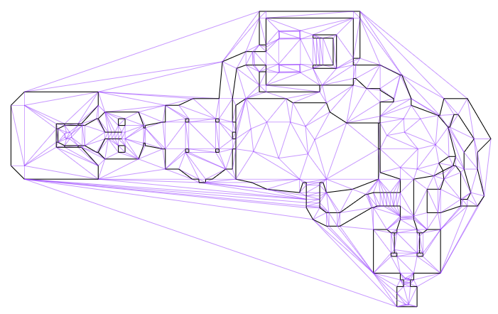
Delaunay meshes are triangle meshes in which we try to keep the triangles as equilateral as possible (to avoid very fractured / long and narrow tiles). Constrained Delaunay meshes are the same thing, except we force certain edges to exist. This makes these meshes useful for things like representing map geometry, where we force walls to be edges in the mesh:

The E1M1 map from DOOM, after I’ve loaded it into a constrained Delaunay mesh

I actually advised that one use constrained Delaunay meshes for 2D player movement in this previous blog post. I hadn’t initially followed my own suggestion because the mesh is dependent on both the level geometry and the player collider (each polygon is expanded by the player collider via a Minkowski sum). If the player ducks and their collider shrinks, then we have to change our mesh. If an enemy has a different sized collider, then it should use a different mesh. If a piece of level geometry moves, such as a platform or door, then we need to change the mesh. All of these problems are still problems, but I’ll have to find workarounds for them. Nevertheless, I’m going with exactly what I spelled out in that earlier blog post.

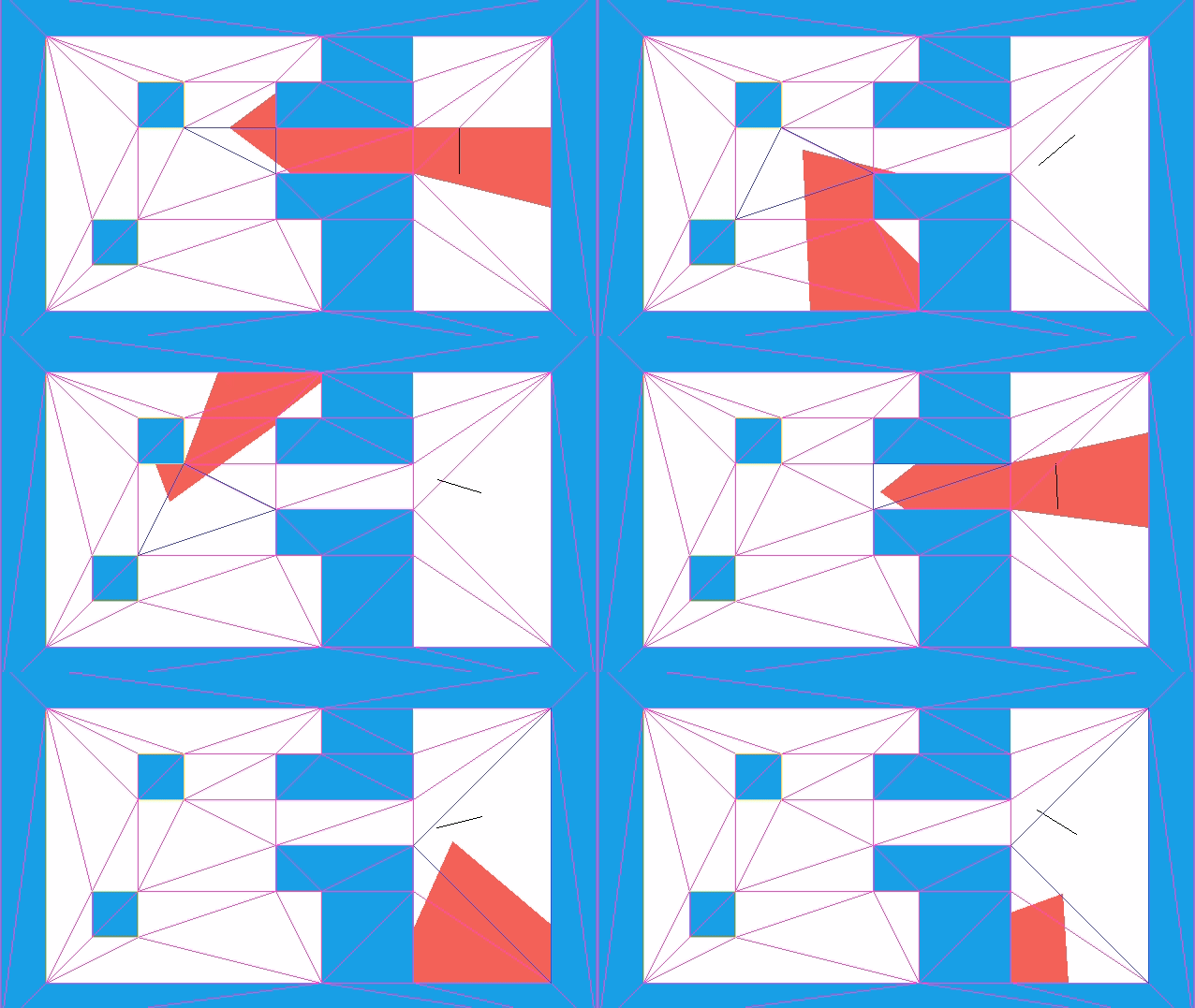
My new plan was to keep track of both the player’s position and the triangle the collision mesh that they find themselves in. The collision mesh already accounts for the player’s collision volume, so we need only keep track of their center position. When they move, we check to see if their motion would take then out of their containing triangle, and if it does, we handle collisions (if necessary) at the crossed edge.

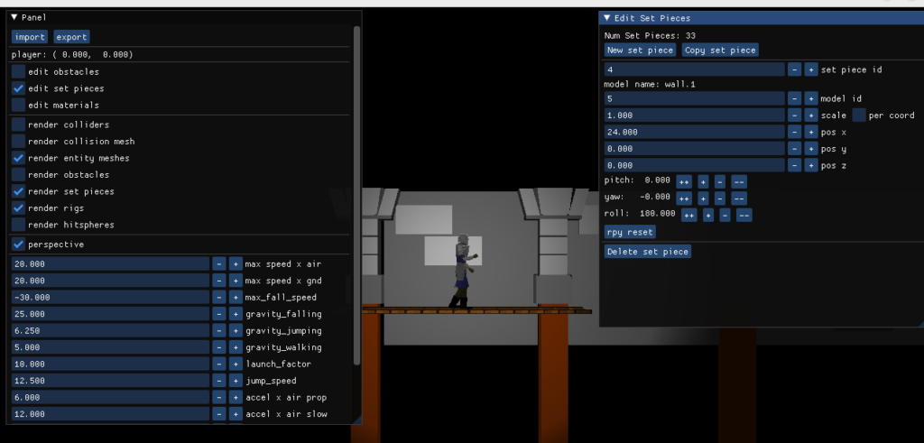
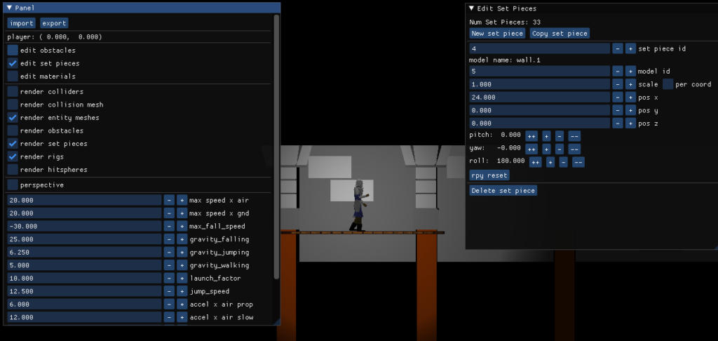
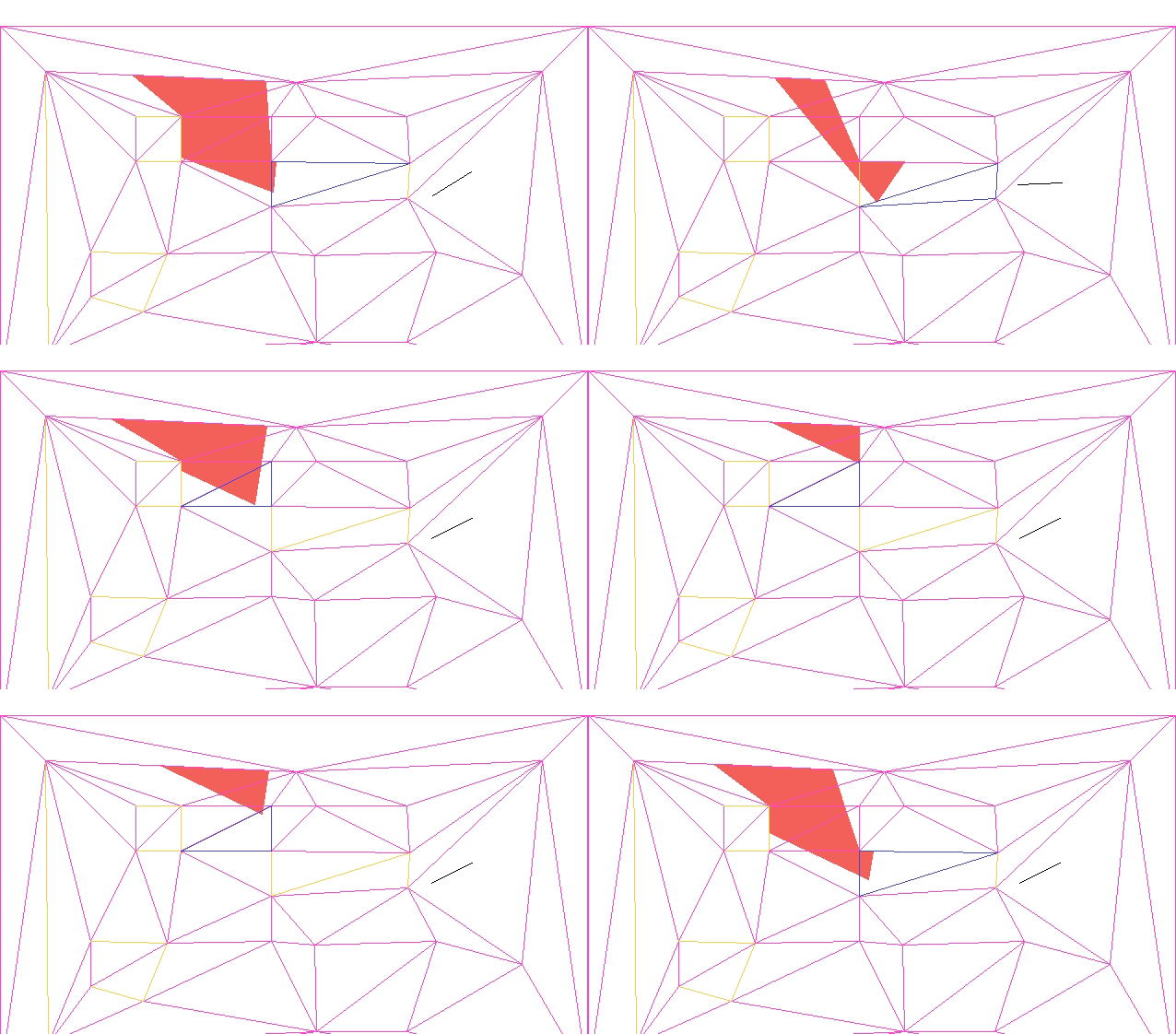
Here we see the updated system, along with the collision mesh.

Building the Mesh

Since I’ve covered how the movement works before, I’d rather focus on how we get the mesh.

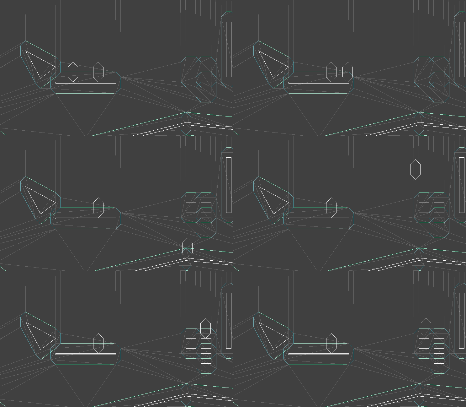
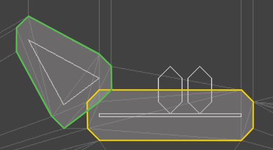
This mesh is obtained by expanding each polygon by the player’s collision volume, and then adding all resulting edges to the Delaunay mesh. These edges are constrained to ensure that they remain in the final mesh (otherwise, we might flip edges in order to make them more equilateral). The main difficulty arises in the fact that the edges of the expanded polygons may intersect, and we nevertheless have to support them in our final mesh:

For example, these expanded polygons overlap.

I had previously tackled this using polygon unions via Clipper2. I could do that again, but want to avoid the loss of information that comes with replacing two or more overlapping polygons with a single polygon. For example, I might want to know which feature my player is standing on. For example, I may end up wanting to support removing objects. Plus, figuring out my own solution is a reward unto itself.

What I ended up doing was updating my method for constraining edges in a DCEL. During the development of TOOM, I had made it possible to load the DOOM level geometry and constrain the appropriate edges. Here we just added sides as we went, and constrained them after adding them:

for (Linedef linedef : linedefs) {
     // Insert vertex a and b.
     for (i16 i_vertex : {linedef.i_vertex_start, linedef.i_vertex_end}) {
         const common::Vec2f& v = doom_vertices[i_vertex];
         InsertVertexResult res = mesh.InsertVertex(v);
         if (res.category == IN_FACE || res.category == ON_EDGE) {
             mesh.EnforceLocallyDelaunay(res.i_qe);
             vertex_indices[i_vertex] = mesh.GetVertexIndex(res.i_qe);
         }
     }

     // Now ensure that there is a line between A and B.
     // If there is not, flip edges until there is.
     QuarterEdgeIndex qe_a =
        mesh.GetQuarterEdge(vertex_indices[linedef.i_vertex_start]);
     QuarterEdgeIndex qe_b =
        mesh.GetQuarterEdge(vertex_indices[linedef.i_vertex_end]);
     QuarterEdgeIndex qe_ab = mesh.EnforceEdge(qe_a, qe_b);
     mesh.ConstrainEdge(qe_ab);

     // sidedef and passability stuff...
}

For example, we might add the vertices for A and B, and then end up with a mesh that is locally Delaunay but does not have an edge between A and B:

The call to EnforceEdge then flips CD in order to get the edge we want:

This approach worked for the DOOM maps because the sides there never crossed over one another. For example, if CD is another enforced edge, there was no way to also enforce AB by flipping edges:

I needed a more general way to specify two points A and B and then adjust the mesh such that those two points are joined by a straight line, potentially via multiple colinear segments.

The updated algorithm has an outer loop that alternately tries tackling the problem from A to B and from B to A. As soon as it finds or produces a connection, it terminates. If it fails to make progress from both directions, it exits out.

Attempting to make progress from A to B starts by finding the edge from A that is as close as possible in a counter-clockwise / right-hand sense to the desired segment AB:

We’ll call the other side of this segment C. If C = B, we are done, as then AB already exists.

It is possible that C lies along AB. When this happens, we replace A with C and return to the outer loop:

If we haven’t returned yet, then AC is counter-clockwise of AB. We need to flip CD, where D is on the other side of AB from C. If CD is not constrained, we can flip it.

The most interesting case occurs when CD is constrained. We cannot flip CD because it is fixed – we want it to remain an edge in the final mesh. So we instead introduce a new point E at the intersection of AB and CD, split CD at E, and add AE and EB:

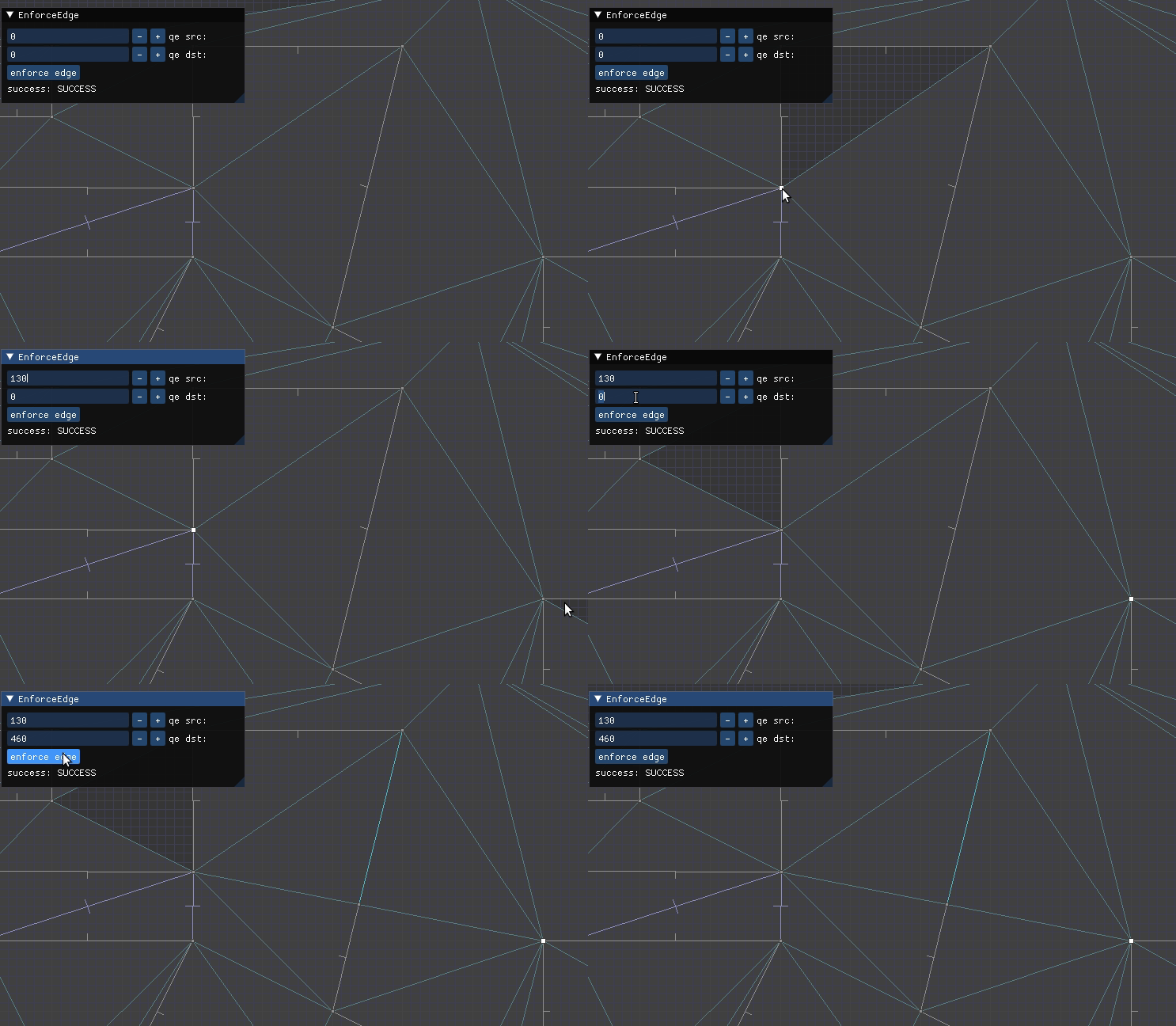
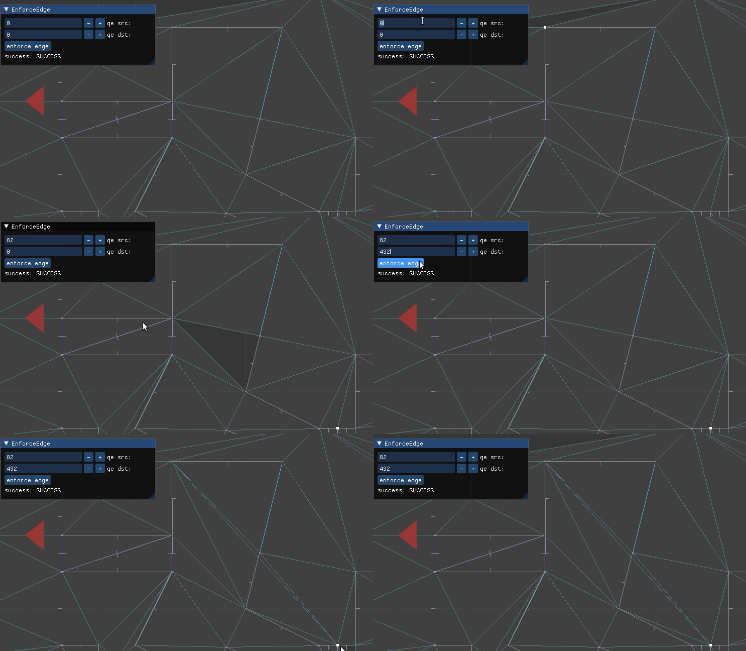
We can see this in action in the TOOM mesh editor, updated with this method:

Here we have a constrained edge

Here we have to flip or intersect multiple edges

So far I’m just building a mesh with constrained edges matching those of the expanded collision polygons, and only have a single such mesh to reflect the player’s collision polygon. I do not yet track which polygon corresponds to which triangle, nor do edges otherwise have any special properties. Nevertheless, what I have is sufficient for basic 2D player movement.

The player (and any other entity) has a 2D position and a triangle face in which their position lies. The 2D position is continuous, but the triangle face is discrete. Having something discrete resolves the issue with floating point rounding – we know exactly which side of a line we are (supposed to be) on.

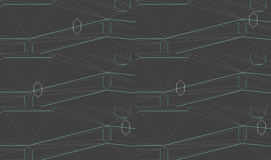
Note that the constrained Delaunay mesh does not actually contain the white collider polygons:

I’ll probably talk about this more next time, but movement physics currently get processed in two different ways. If the moving entity is airborne, then they move according to the standard laws of physics. If we collide with a solid edge, we lose all velocity going into it and then continue on in our new direction. Colliding with a solid edge can result in the agent transitioning to the supported state.

If the moving entity is standing or walking on a surface, i.e. is supported, we handle things a bit differently. Here their velocity is projected along the supporting surface. Any time they move past the end of the supporting surface, we find the next supporting edge (if there is one) and allow them to transition over. If they are moving fast enough or there is no supporting edge to connect to, they transition to being airborne.

The player walking across supporting surfaces

Conclusion

Constrained Delaunay meshes resolved many of the tricky issues that arose with tackling 2D player movement for arbitrary terrain geometry. Knowing which face a player is in is a discrete fact that removes the issues with numeric imprecision in general polygon-on-polygon collisions, without having to resort to shunting. It also naturally allows us to leverage the mesh to query things like the next supporting face.

The code for the updated Delaunay mesh is available here.

In the future I hope to support additional motion states, such as climbing on ladders and surfaces. I’ll want to add support for dropping down “through” a platform, wall slides and jumps, and some other basic sidescroller movement features. I want to add 3D GPU graphics, and with that, animations and combat. It turns out there is a lot that goes into a basic game.

Optimization is Ax = b

One of the most interesting parts of the Convex Optimization lectures by Stephen Boyd was the realization that (continuous) optimization more-or-less boils down to repeatedly solving Ax = b. I found this quite interesting and thought I’d write a little post about it.

Constrained Optimization

An inequality-constrained optimization problem has the form:

\[\begin{aligned}\underset{\boldsymbol{x}}{\text{minimize}} & & f(\boldsymbol{x}) \\ \text{subject to} & & \boldsymbol{g}(\boldsymbol{x}) \leq \boldsymbol{0}\end{aligned}\]

One popular algorithm for solving this problem is the interior point method, which applies a penalty function that prevents iterates \(\boldsymbol{x}^{(k)}\) from becoming infeasible. One common penality function is the log barrier, which transforms our constrained optimization problem into an unconstrained optimization problem:

\[\underset{\boldsymbol{x}}{\text{minimize}} \enspace f(\boldsymbol x) \> – \> \frac{1}{\rho}
\sum_i \begin{cases}
\log\left(-g_i(\boldsymbol x)\right) & \text{if } g_i(\boldsymbol x) \geq -1 \\
0 & \text{otherwise}
\end{cases}\]

or even just

\[\underset{\boldsymbol{x}}{\text{minimize}} \enspace f(\boldsymbol x) \> – \> \frac{1}{\rho}
\sum_i \log\left(-g_i(\boldsymbol x)\right)\]

The penalty scalar \(\rho > 0\) starts small and is increased as we iterate, reducing the penalty for approaching the constraint boundary.

We thus solve our constrained optimization problem by starting with some feasible \(\boldsymbol x^{(0)}\) and then solving a series of unconstrained optimizations. So the first takeaway is that constrained optimization is often solved with iterated unconstrained optimization.

Here we see the an objective function (blue) constrained with \(x \geq 1\) (gray line). The red line shows the penalized surrogate objective. As we increase \(\rho\) and optimize, our solution moves closer and closer to \(x = 1\).

Unconstrained Optimizaton

We have found that constrained optimization can be solved by solving a series of unconstrained optimization problems.

An unconstrained optimization problem has the form:

\[\begin{aligned}\underset{\boldsymbol{x}}{\text{minimize}} & & f(\boldsymbol{x}) \end{aligned} \]

If \(f\) is continuous and twice-differentiable, we can solve this problem with Newton’s method. Here we fit a quadratic function using the local gradient and curvature and use its minimum (which we can solve for exactly) as the next iterate:

\[\boldsymbol x^{(k+1)} = \boldsymbol x^{(k)} \> – \> \boldsymbol H(\boldsymbol x^{(k)})^{-1} \nabla f(x^{(k)})\]

Continuous functions tend to become bowl-shaped close to their optimas, so Newton’s method tends to converge extremely quickly once we get close. Here is how that looks on the banana function:

What this means is that unconstrained optimization is done by repeatedly calculating Newton steps. Calculating \(\boldsymbol H(\boldsymbol x^{(k)})^{-1} \nabla f(x^{(k)})\) is the same as solving Ax = b:

\[\boldsymbol H\boldsymbol d = \nabla f\]

Well alrighty then, optimization is indeed a bunch of Ax = b.

What does this Mean

There are several takeaways.

One is that its nice that complicated things are just made up of simpler things that we can understand. One can take comfort in knowing that the world is understandable.

Another is that we should pay a lot of attention to how we compute Ax = b. Most of our time spent optimizing is spent solving Ax = b. If we can do that more efficiently, then we can optimize a whole lot faster.

Estimating Solve Times

How long does it take to solve Ax = b? Well, that depends. Let’s say we’re naive, and we have a random \(n \times n\) matrix \(\boldsymbol A\) and a random vector \(\boldsymbol b\). How fast can our computers solve that?

Well, it turns out that my laptop can solve a random \(1000 \times 1000\) linear system in about 0.35s:

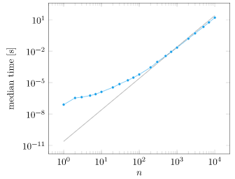
We can plot the computation time vs. matrix size:

At first glance, what we see is that yes, computation grows as we increase \(n\). Things get a little fishy though. That trend line is \(n^2/10^7\), which is not the \(O(n^2)\) growth that we expected. What is going on?

While Julia itself is running single-threaded, the underlying BLAS library can use up to 8 threads:

Our system is sneakily making things more efficient! If we force BLAS to be single-threaded, we get the \(O(n^3)\) growth we expected after about \(n=200\) (Thank you Julia Discourse!):

What we’ve learned is pretty important – there are speedups to be had that go beyond traditional big-O notation. If you have an optimization problem, chances are that multithreading and SIMD can speed things up for you. If you have a really large optimization problem, maybe you can distribute it across multiple machines (Proximal methods, for example, are often amenable to this).

We also learned how mind-bogglingly fast linear algebra is, even on a single thread. Think about how long it would take you to manually solve Ax = b for \(n=2\) with pen and paper, and how fast the same operation would take on your machine.

If it takes 100 Newton iterates to solve an unconstrained optimization problem, then you can solve a problem with a thousand variables in 3.5s. Multiply that by another 100 for a constrained optimization problem, and you’re looking at solving a constrained optimization problem with \(n=1000\) in under 6 minutes (and often in practice, much faster).

We live in an era where we can solve extremely large problems (GPT-4 is estimated to have 1.7 billion parameters), but we can also solve smaller problems really quickly. As engineers and designers, we should feel empowered to leverage these capabilities to improve everything.

Special Structure

Appendix C of Convex Optimization talks a lot about how to solve Ax = b. For starters, generally solving \(\boldsymbol A \boldsymbol x = \boldsymbol b\) for an arbitrary \(\boldsymbol A \in \mathbb{R}^n\) and \(\boldsymbol b \in \mathbb{R}^n\) is \(O(n^3)\). When we’re using Newton’s method, we know that the Hessian is symmetric and positive definite, so we can compute the Cholesky decomposition of \(\boldsymbol A = \boldsymbol F^\top \boldsymbol F\). Overall, this takes about half as many flops as Gaussian elimination [source].

There are a bunch of other types of structure that we can take advantage of when we know that it exists. The most obvious is when \(\boldsymbol A\) is diagonal, in which case solving Ax = b is \(O(n)\).

One particularly interesting example is when \(\boldsymbol A\) has arrow structure:

When this happens, we have to solve:

\[\begin{bmatrix} \boldsymbol A & \boldsymbol B \\ \boldsymbol B^\top & \boldsymbol C \end{bmatrix} \begin{bmatrix} \boldsymbol x \\ \boldsymbol y \end{bmatrix} = \begin{bmatrix}\boldsymbol b \\ \boldsymbol c\end{bmatrix}\]
where \( \boldsymbol A\) is diagonal, block-diagonal, or banded; \(\boldsymbol B\) is long and narrow; and \(\boldsymbol C\) is dense but comparatively small.

Solving a system with arrow structure can be done by first solving \(\boldsymbol A \boldsymbol u = \boldsymbol b\) and \(\boldsymbol A \boldsymbol V = \boldsymbol B\), which are both fast because we can exploit \( \boldsymbol A\)’s structure. Expanding the top row and solving gives us:

\[\boldsymbol x = \boldsymbol A^{-1} \left( \boldsymbol b – \boldsymbol B \boldsymbol y \right) = \boldsymbol u \> – \boldsymbol V \boldsymbol y\]

We can substitute this into the bottom row to get:

\[\begin{aligned} \boldsymbol B^\top \boldsymbol x + \boldsymbol C \boldsymbol y & = \boldsymbol c \\ \boldsymbol B^\top \left( \boldsymbol u \> – \boldsymbol V \boldsymbol y \right) + \boldsymbol C \boldsymbol y & = \boldsymbol c \\ \left( \boldsymbol C – \boldsymbol B^\top \boldsymbol V\right) \boldsymbol y & = \boldsymbol c \> – \boldsymbol B^\top \boldsymbol u\end{aligned}\]

Having solved that dense system of equations for \(\boldsymbol y\), we can back out \(\boldsymbol x\) from the first equation and we’re done.

You might think that arrow structure is a niche nicety that never actually happens. Well, if you look at how packages like Convex.jl, cvx, and cvxpy solve convex optimization problems, you’ll find that they expand and transform their input problems into a partitioned canonical form:

\[\begin{aligned}\underset{\boldsymbol x^{(1)}, \ldots, \boldsymbol x^{(k)}}{\text{minimize}} & & d + \sum_{i=1}^k \left(c^{(i)}\right)^\top \boldsymbol x^{(i)} \\ \text{subject to} & & \boldsymbol x^{(i)} \in \mathcal{S}^{(i)} \enspace \text{for } i \text{ in } \{1, \ldots, k\}\\ & & \sum_{i=1}^k \boldsymbol A^{(i)} \boldsymbol x^{(i)} = \boldsymbol b\end{aligned}\]

If we apply an interior point method to this:

\[\begin{aligned}\underset{\boldsymbol x}{\text{minimize}} & & d + \boldsymbol c^\top \boldsymbol x + \frac{1}{\rho} p_\text{barrier}(\boldsymbol x) \\ \text{subject to} & & \boldsymbol A^\top \boldsymbol x = \boldsymbol b\end{aligned}\]

we can apply a primal-dual version of Newton’s method that finds a search direction for both \(\boldsymbol x\) and the dual variables \(\boldsymbol \mu\) by solving:

\[\begin{bmatrix} \nabla^2 p_\text{barrier}(\boldsymbol x) & \boldsymbol A^\top \\ \boldsymbol A & \boldsymbol 0\end{bmatrix} \begin{bmatrix}\Delta \boldsymbol x \\ \boldsymbol \mu \end{bmatrix} = – \begin{bmatrix}\rho \boldsymbol c + \nabla p_\text{barrier}(\boldsymbol x) \\ \boldsymbol A \boldsymbol x – \boldsymbol b\end{bmatrix}\]

Wait, what is that we see here? Not only does this have arrow structure (The Hessian matrix \(\nabla^2 p_\text{barrier}(\boldsymbol x)\) is block-diagonal), but the tip of the arrow is zero! We can thus solve for the Newton step very efficiently, even for very large \(n\).

So this esoteric arrow-structure thing turns out to be applicable to general convex optimization.

Conclusion

If you take a look at university course listings, there is a clear pattern of having classes for “Linear X” and “Nonlinear X”. For example, “EE263: Introduction to Linear Dynamical Systems” and “E209B Advanced Nonlinear Control”. You learn the linear version first. Why? Because we’re really good at solving linear problems, so whenever a problem can be framed or approximated in a linear sense, we’ve either solved it that way first or found its easiest to teach it that way first. Anything can be locally approximated by a 1st-order Taylor series and we can just work with a linear system of equations.

I love that insight, but I also love the implication that it has. If we can understand how to work with linear systems, how to exploit their structure and how to solve them quickly to sufficient accuracy, then we can speed up the solution of pretty much any problem we care about. That means we can solve pretty much any problem we care about better, more often, to a higher-degree of precision, and thereby make the world a better place.

Global Path Planning and Local Refinement

We often want robots, drones, or video game mobs to navigate from one location to another as efficiently as possible, without running into anything.

In such times of need, many of us turn to A*, in which we discretize our problem and make path planning about finding a sequence of discrete steps. But that only solves half the problem – we often end up with a chunky, often zig-zaggy solution:

The actual shortest path doesn’t look like that. It hugs the corners and moves off-axis:

This post will cover one way to solve this problem. It will continue to leverage the power of graph algorithms like A*, but will conduct local path optimization in the second phase to get a shortest path.

Phase 1: Global, Discrete Path Planning

In the first phase, we find a coarse shortest path through a graph. Graphs are incredibly useful, and let us apply discrete approaches to the otherwise continuous world.

For this to work, the planning environment has to be represented as a graph. There are many ways to achieve this, the simplest of which is to just use a grid:

From Optimal Target Assignment and Path Finding for Teams of Agents, showing a Kiva warehouse layout.

For more general terrain it is more common to have tessellated geometry, often in the form of a navigation mesh. Below we see a path for a marine in a StarCraft 2 navmesh:

From RTS Pathfinding 3 by jdxdev, who in turn got it from Pathing it’s not a solved Problem

I first talked about navigation meshes in my post about Delaunay triangulations, and I’ve been using them to represent my game map geometry in TOOM.

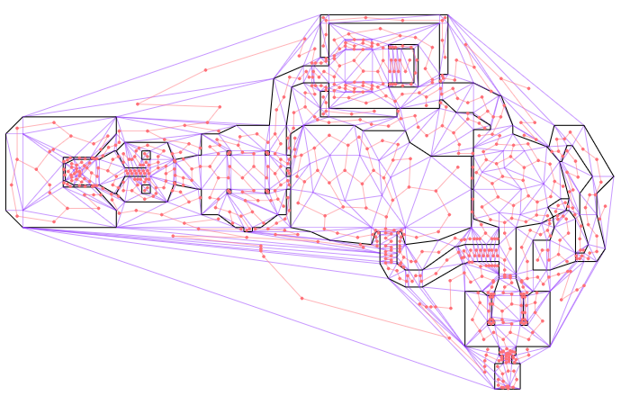
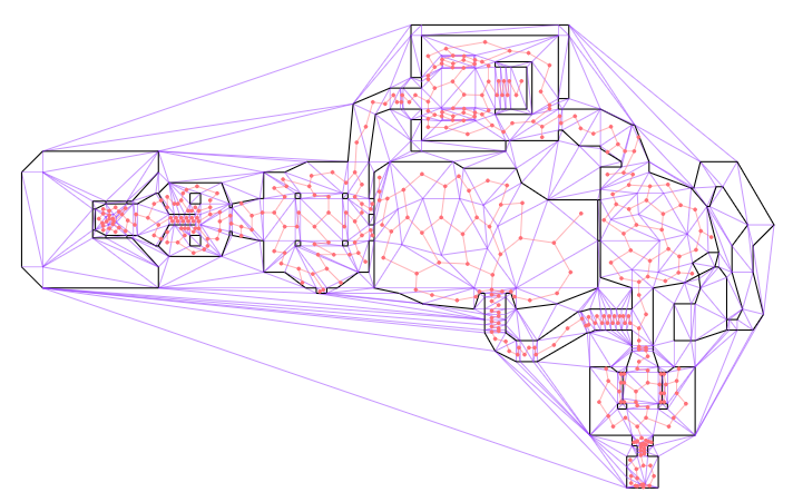
Navigation meshes, typically represented using doubly connected edge lists (DCELs), are graphs that represent both the geometry (via primal vertices and edges), and connections between faces (via dual vertices and edges). This sounds more complicated than it is. Below we see the E1M1 map from DOOM, after I’ve loaded it into a DCEL. The map walls are black and the remaining triangle edges are shown in purple:

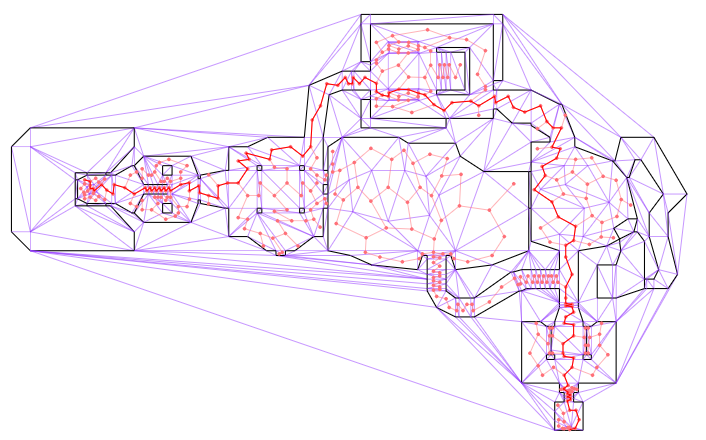
This image above only shows the primal graph, that is, the actual map geometry. The cool thing about DCELs is that they also contain a dual graph that represents connectivity between faces (triangles). Below I additionally show that dual graph in red. I’ve ignored any edges that are not traversible by the player (i.e. walls or large z changes):

The first phase of path planning is to find the shortest path in this dual graph from our source triangle to our destination triangle. We can drop nodes that aren’t reachable:

We can run a standard graph-search algorithm on this dual graph. Each node lies at the centroid of its triangular face, and the distance between nodes can simply be the distance between the centroids. As the problem designer, you can of course adjust this as needed – maybe walking through nukage should cost more than walking over normal terrain.

In Julia this can be as simple as tossing the graph to Graphs.jl:

shortest_paths = dijkstra_shortest_paths(g, [i_src], edge_distances)

This gives us a shortest path through the triangulated environment. It is typically jagged because it can only jump between centroids. Below we see a shortest path that traverses the map:

The discrete phase of motion planning is typically very efficient, because graph search algorithms like A* or Dijkstra’s algorithm are very efficient. If our environment is more or less static, we can even precompute all shortest paths. This makes the discrete phase of motion planning very cheap.

Our problem, however, is that the resulting path is not refined. To rectify that, we need a second, local phase.

Phase 2: Local Refinement

The second phase of path planning takes our discrete path and cleans it up. Where before we were constrained to the nodes in the dual graph, in this phase we will be able to shape our path more continuously. However, we will restrain our path to continue to traverse the same sequence of faces as it did before.

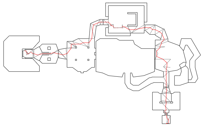
Because we are restricting ourselves to the same sequence of faces, we can ignore the rest of the graph. The first thing we’ll do is switch from traversing between centroids to traversing between edges along a specific corridor. Below we show the path slightly modified (red), with traversals between the centers of the crossed faces (gray):

That is already somewhat better, but it is not good enough. Next we will shift these crossing points along the crossed edges in order to shorten the path. This can be thought if as laying down a long rubber band along the center of the traversed corridor, and then stretching it out to tighten it so that it hugs the edges. As such, this process is often called elastic band optimization or string pulling.

This is an optimization problem. How do we formulate it?

Let \(\boldsymbol{p}^{(0)}\) be our starting point, \(\boldsymbol{p}^{(n+1)}\) be our destination point, and \(\boldsymbol{p}^{(i)}\) for \(i\) in \(1:n\) be the \(n\) vertices at the edges that our path traverses. We can slide each \(\boldsymbol{p}^{(i)}\) along its edge, between its leftmost and rightmost values:

\[\boldsymbol{p}^{(i)} = \alpha_i \boldsymbol{p}_\ell^{(i)} + (1-\alpha_i)\boldsymbol{p}_r^{(i)} \]

Each interpolant \(\alpha_i\) ranges from 0 to 1. Below we depict a handful of these:

We are trying to minimize the total path length, which is the sum of the distances between sequential points:

\[\sum_{i=0}^n \| \boldsymbol{p}^{(i+1)} – \boldsymbol{p}^{(i)} \|_2\]

which in 2D is just:

\[\sum_{i=0}^n \sqrt{(\boldsymbol{p}^{(i+1)}_x – \boldsymbol{p}^{(i)}_x)^2 + (\boldsymbol{p}^{(i+1)}_y – \boldsymbol{p}^{(i)}_y)^2}\]

Our optimization problem is thus:

\[\begin{aligned}\underset{\boldsymbol{\alpha}_{1:n}}{\text{minimize}} & & \sum_{i=0}^n \| \boldsymbol{p}^{(i+1)} – \boldsymbol{p}^{(i)} \|_2 \\ \text{subject to} & & \boldsymbol{p}^{(i)} = \alpha_i \boldsymbol{p}_\ell^{(i)} + (1 – \alpha_i) \boldsymbol{p}_r^{(i)} \\ & & \boldsymbol{0} \leq \boldsymbol{\alpha} \leq \boldsymbol{1} \end{aligned}\]

This problem is convex because \(\| \boldsymbol{p}^{(i+1)} – \boldsymbol{p}^{(i)} \|_2\) is convex and the sum of convex functions is convex, the first constraint is linear (which is convex), and the inequality constraints are simple inequality constraints. We can thus solve this problem exactly.

In a game engine or robotics product we might roll our own solver, but here I’m just going to use Convex.jl:

α = Variable(n)     # interpolants
ps = Variable(2, n) # optimized points, including endpoints

problem = minimize(sum(norm(ps[:,i+1] - ps[:,i]) for i in 1:n-1))
for i in 1:n
    problem.constraints += ps[:,i] == p_ls[i] + α[i]*(p_rs[i] - p_ls[i])
end
problem.constraints += α >= 0
problem.constraints += α <= 1

solve!(problem, () -> ECOS.Optimizer(), verbose=false, silent_solver=true)

α_val = evaluate(α)
ps_opt = evaluate(ps) 

Easy!

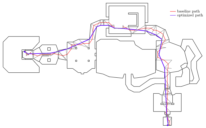
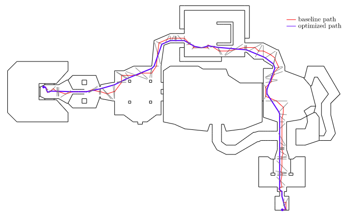
Solving our optimization problem gives us our locally-optimized shortest path:

We can see how the optimized path hugs the corners and walls and heads straight across open areas. That is exactly what we want!

Agents have Width

Okay, so this gives us an optimized path, but it treats our robot / drone / enemy unit as a point mass. Our agents typically are not point masses, but have some sort of width to them. Can we handle that?

Let’s treat our agent as being a circle with radius \(r\). You can see such a circle in the earlier image for the StarCraft 2 marine.

We now modify both phases of our path planning algorithm. Phase 1 now has to ignore edges that are not at least \(2r\) across. Our agent cannot fit through anything more narrow than that. We set the path traversal cost for such edges to infinity, or remove them from the graph altogether.

Phase 2 has the more radical change. We now adjust the leftmost and rightmost points \(\boldsymbol{p}_\ell^{(1:n)}\) and \(\boldsymbol{p}_r^{(1:n)}\) to be a distance \(r\) from the line segment endpoints. This reflects the fact that our agent, with radius \(r\), cannot get closer than \(r\) to the edge of the crossed segment.

Below we show an optimized path using a small player radius. We can see how the new path continues to try to hug the walls, but maintains at least that fixed offset:

Notice that this naive augmentation introduced a few artifacts into the smoothed path, particularly near the start and end vertices. This stems from the fact that the map geometry in those location includes edges that are not actually constrained by walls on both sides. For example, the room in the bottom right has some extra triangles in order to be able to carve out that exit sign in the ceiling. It doesn’t actually hamper movement:

This can be fixed by using a navigation mesh that more accurately reflects player navigation. In this case, we’d remove the exit sign from the nav mesh and end up with an exit room where every edge has vertices that end at the walls.

Conclusion

This post covered a method for path planning applicable to basic robotics motion planning or for AI path planning in video games. It is a two-phase approach that separates the problem into broadly finding the homotopy of the shortest path (which side of a thing to pass on) and locally optimizing that path to find the best continuous path within the identified corridor. This method of breaking down the problem often shows up when tackling complicated problems – a discrete solver is often better at the big-picture and a local optimizer is often better for (often much-needed) local refinement.

There are many variations to the path planning problem. For example, path planning for a robot car may require restricting our path to allow for a certain turning radius, and path planning for an airplane may require planning in 3D and restricting our climb or descent rates. We may wish to minimize things other than the path distance, such as the amount of energy required, or find the shortest path that gets us there within a given energy budget. The real world is full of complexity, and having the necessary building blocks to construct your problem and the various tools at your disposal to solve them in the way that makes most sense for you makes all the difference.

TOOM with Non-Euclidean Geometry

This month continues our foray into the world of DOOM and C software renderers. In the last post, we moved from a blocky, axis-aligned world to general 2D geometry. In this post, not only will we manipulate the 3rd dimension, thereby reaching DOOM-geometry-parity, we will leverage our raycasting approach to unlock something the original DOOM couldn’t do.

Variable Floor and Ceiling Heights

In Wolfenstein 3D, the floors are always at z = 0 and the ceilings are always at z = 1. DOOM could adjust these floor and ceiling heights, and its players were thus able to ascend stairs, traverse next to chasms, and generally enjoy a much richer gaming environment.

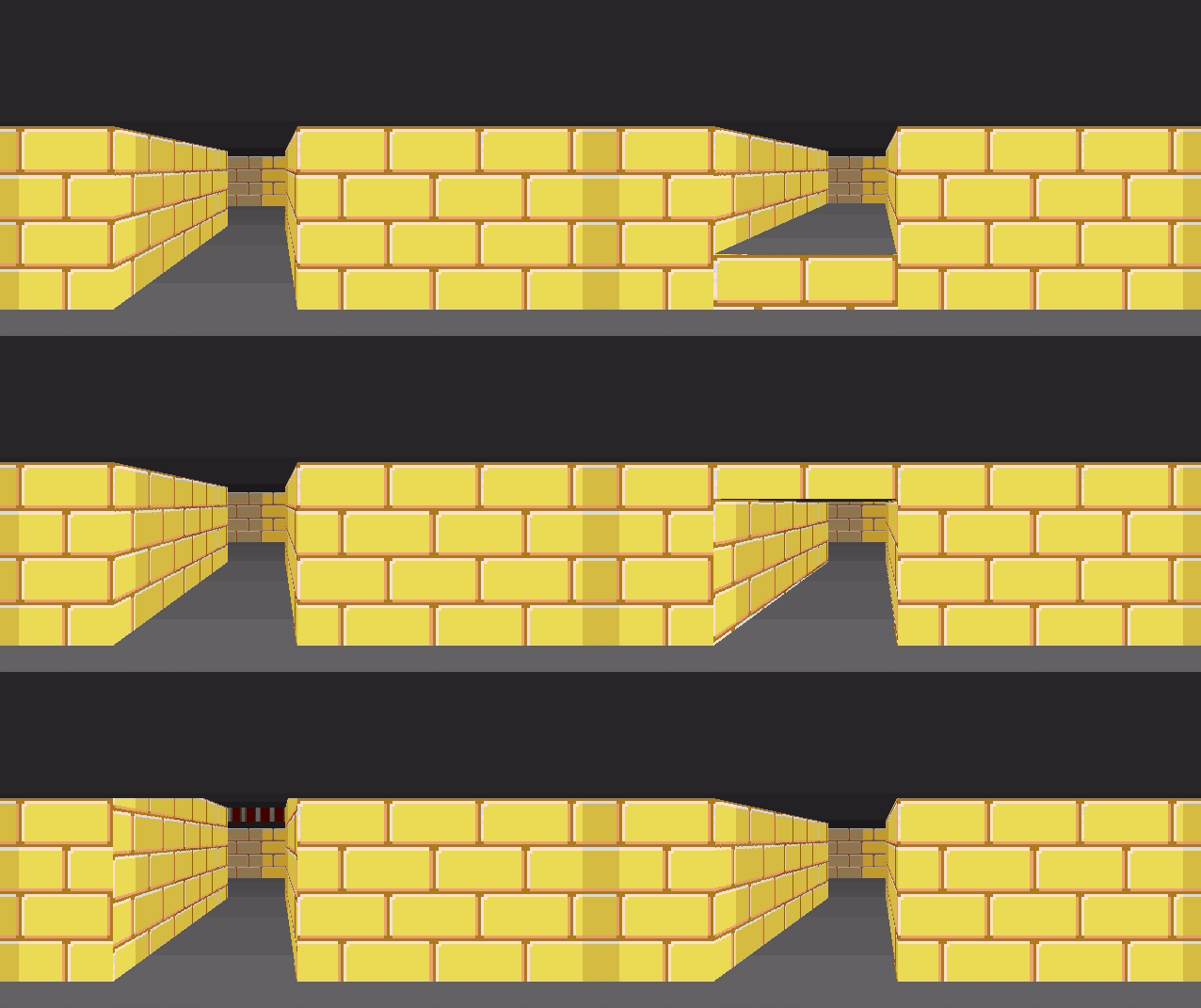
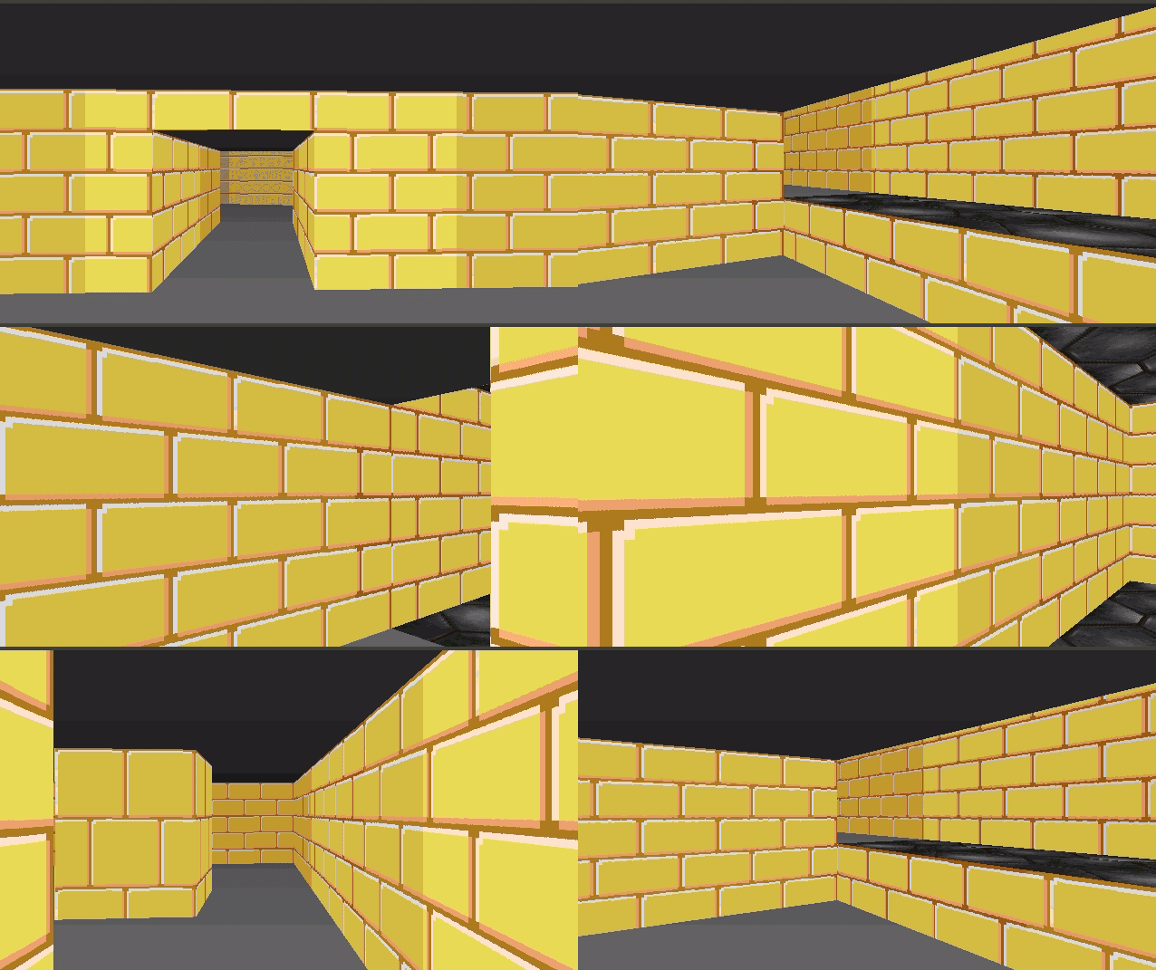
This gif shows the basic z-manipulation I’m talking about:

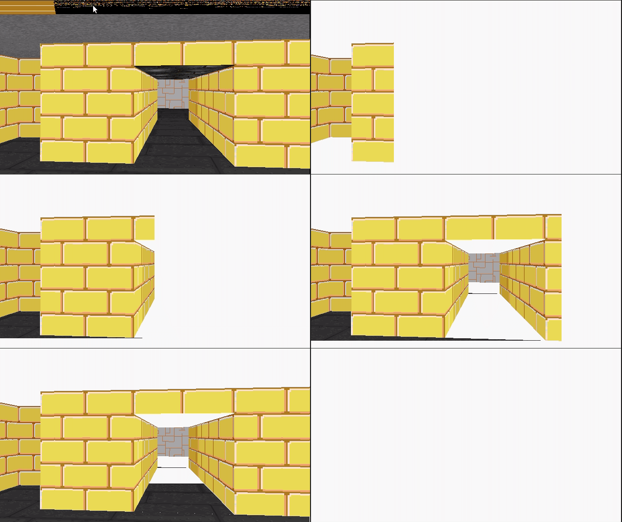
Here we’re adjusting the floor and ceiling height of our corridor. When we raise the floor, we need to render a wall texture between our floor and the raised corridor floor. When we lower the floor, we need to render a wall texture between the lowered floor and the normal floor on the other end.

Changing the ceiling height can also expose a bit of wall texture:

Our renderer has to be able to model these floor sections in order to keep track which of piece of floor has which floor and ceiling height, and we have to keep track of the textures to draw when they are exposed.

Like DOOM, I will denote regions of the map with a particular floor and ceiling height (and later, floor and ceiling textures) to be called a sector. Sectors will naturally be closed polygons in our top-down 2D map.

Here you can see a top-down view of the TOOM level editor, showing the same region as rendered above. The red triangle is the camera, which looks toward the right.

Here is the same shot, filled in a bit to make it easier to interpret:

As covered in the last post, the world is defined using a triangle mesh. Our corridor, for example, is comprised of two triangles. The sector for that corridor must be referenced by the lines along the corridor’s boundary:

The sector itself just stores the z heights right now. It doesn’t know which edges it corresponds to. Instead, we have the side geometry refer to the sector it should correspond to. This approach is again, very much like DOOM.

We are using a Doubly Connected Edge List (DCEL) to represent our triangle mesh. Edges in a DCEL are bi-directional . If we think of edges as right-handed, and an edge A->B as being on the right-hand side of AB, then we can just have every directed edge at the boundary of a sector keep track of which sector it helps enclose.

The sides that refer to the corridor are yellow, whereas the sides that refer to the primary sector are orange. When we raycast from the camera down the corridor, we can check for z changes when we traverse over edges where the sector changes. Here we see a raycast with two locations where the sector heights might change:

The data structures for this are pretty simple. A directed edge may have a SideInfo:

struct SideInfo {
    u16 flags;
    u16 sector_id;
    TextureInfo texture_info_lower;
    TextureInfo texture_info_middle;
    TextureInfo texture_info_upper;
};

A SideInfo is simply a struct that contains a lower, middle, and upper texture, the index of the sector to refer to, and some flags. Right now, the only flag I use is one to determine whether a wall is passable, and if so, we can avoid rendering the middle texture.

The TextureInfo entry is pretty simple as well:

struct TextureInfo {
    u16 texture_id; // Index in the texture atlas
    i16 x_offset;   // Texture x offset
    i16 y_offset;   // Texture y offset
};

And Sectors are just basic data as well:

struct Sector
{
    u16 flags;
    f32 z_floor;
    f32 z_ceil;
};

Raycasting with Varying Heights

With these data structures in-hand, rendering becomes a little more complicated. We continue to cast our ray out, as before. Now, however, we need to keep track of how much we’ve already drawn.

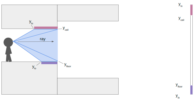
To illustrate, let’s look at a horizontal cross-section of geometry:

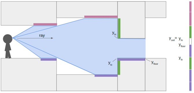
Here I have drawn the area swept out as we cast a single ray to the right, down a single pixel-column. The light purple boxes show all of the regions in our field-of-view where we need to render ceiling pixels, the dark purple boxes show where we need to render floor pixels, and the green boxes show where we need to render wall pixels.

When we start raycasting, we start having not drawn any pixels. The bounds on where we can draw contains the whole vertical pixel column, between zero and the number of pixels:

\[y_\text{lo} = 0 \qquad y_\text{hi} = \text{SCREEN_SIZE_Y}\]

We start to traverse the mesh, and hit our first sector change:

At this point we calculate the y-location (i.e., location in the vertical pixel column) of the ends of the floor and ceiling. We render the floor and ceiling into our pixel column. We’re already pretty used to this trigonometry by now.

\[\begin{aligned} y_\text{ceil} & = \frac{\text{SCREEN_SIZE_Y}}{2} + \gamma \left( z_\text{ceil} – z_\text{camera} \right) \\ y_\text{floor} & = \frac{\text{SCREEN_SIZE_Y}}{2} + \gamma \left( z_\text{floor} – z_\text{camera} \right)\end{aligned}\]

where

\[\gamma = \frac{\text{SCREEN_SIZE_Y}}{\text{y field of view}} \cdot \frac{\text{cam length}}{\text{ray length}}\]

The y yield of view is how many units up the camera views for every unit we raycast outward. I’m using about 0.84. The camera length is close to 1, and adjusts for the fact that our screen is flat and not curved, so rays travelling left or right of center have to have the length adjusted. Other than that, its just a function of the heights and how far our ray has traveled.

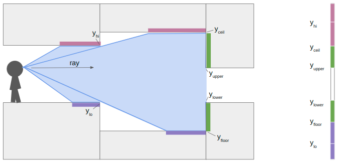
In this case, the next sector has an increase in the ceiling height and a decrease in the floor height. That means we do not have any local wall textures to render. We set \(y_\text{lo} = y_\text{floor}\) and \(y_\text{hi} = y_\text{ceil}\) and keep on raycasting:

At the next sector transition, we once again compute \(y_\text{floor}\) and \(y_\text{ceil}\). This time, however, the ceiling drops and the floor rises, so we also have wall segments to render. We compute their pixel extents in the same way:

\[\begin{aligned} y_\text{upper} & = \frac{\text{SCREEN_SIZE_Y}}{2} + \gamma \left( z_\text{upper} – z_\text{camera} \right) \\ y_\text{lower} & = \frac{\text{SCREEN_SIZE_Y}}{2} + \gamma \left( z_\text{lower} – z_\text{camera} \right)\end{aligned}\]

where \(z_\text{upper}\) and \(z_\text{lower}\) are the new sector ceiling and floor heights, respectively.

When we continue our raycast, we find that the next sector transition only increases the ceiling height. The new \(y_\text{floor}\) is greater than \(y_\text{lo}\), so we render the patch of floor. The new \(y_\text{ceil}\) is not any lower than our current \(y_\text{hi}\), due to the ceiling being parallel to our camera view, so we don’t need to render anything there.

We finally proceed and hit a closed sector. We render the last bit of floor and then render its center texture:

So that’s how the renderer works when you have variable z heights and upper, middle, and lower textures. Each raycast has to do more work to determine what to draw, and it keeps track of where it is within its y pixel bounds to make sure we don’t mistakenly draw something on top of what we’ve already rendered.

Rendering Textures

In this previous blog post, I covered sprites, and how they use the DOOM picture format. In short, sprites like monsters are stored in vertical pixel strips. Why? Because when we render the vertical portions of the world, we’re rendering convenient vertical sections of these sprites. The vertical orientation forms a right-triangle, which makes the math of figuring out which pixel to draw more efficient. DOOM uses the same format for wall textures (both upper and lower). I ended up doing the same thing.

So, wall textures are the same as sprites. What about horizontal textures? We’d like to draw textures on our ceilings and floors too:

(Yeah, these don’t fit thematically. I haven’t loaded my own floor and ceiling textures yet. These just come from DOOM.)

We can again leverage our previous work to figure out how to draw floor and ceiling textures. Unlike the vertically-oriented wall textures, these “flat” textures are most efficiently drawn horizontally across the screen. As such, in DOOM they are called flats.

Our render is most adept at rendering things vertically. It works on one pixel column at a time. So how do we hope to render anything horizontally?

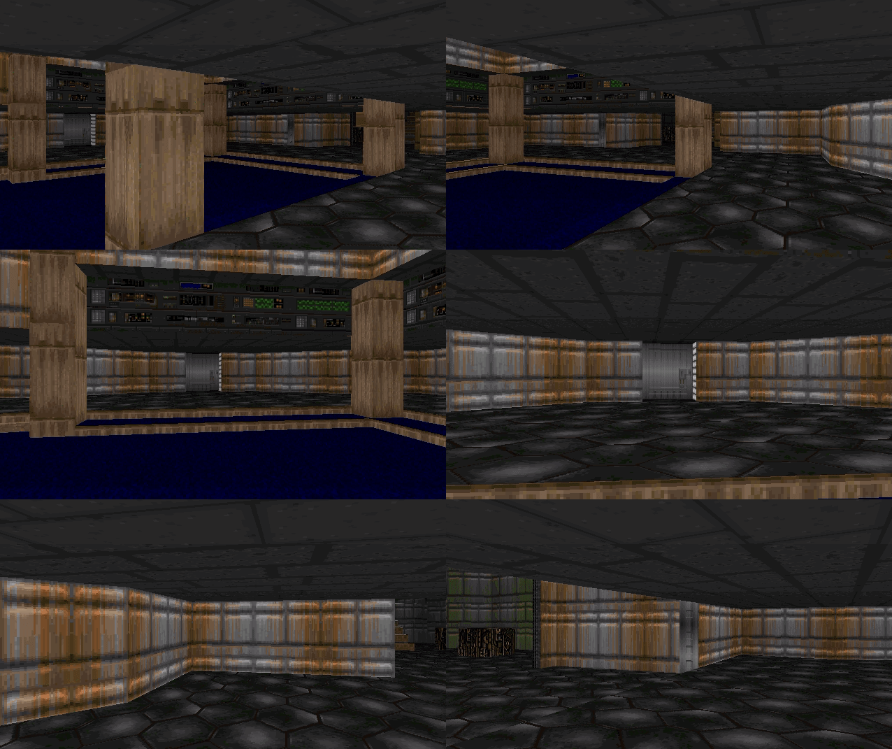
Well, the raycasts start with the leftmost pixel column and then work their way to the right. I keep track of active spans, which are horizontal sections of the screen that need to eventually be rendered with a single flat at a single floor height. Whenever we need to start a new span, we close out the previous one and render it.

The gif above shows how the renderer produces a scene. We draw vertical sections as we raycast, but start/maintain horizontal spans that only get rendered (1) when another span in the same y-coordinate starts or (2) we are done raycasting.

Each active span contains all of the information needed to render it efficienctly, once it needs to be rendered:

struct ActiveSpanData {
    // Location of ray_dir_lo's intersection with the ground.
    common::Vec2f hit;
    // Shift 'hit' by one pix column moved toward hi's intersection.
    common::Vec2f step;
    u16 sector_id;
    u16 flat_id;
    bool is_active;
    // The camera x pixel index where this span starts.
    int x_start;
    // The most recent camera x pixel where this span currently ends.
    int x_end;
};

We can do the computation work of calculating the hit and step values when we first create the span. We set x_start at that time, and initially set x_end to the same value. If we go to render the same sector in the same location in the next column, we increment x_end.

Colors and Light Levels

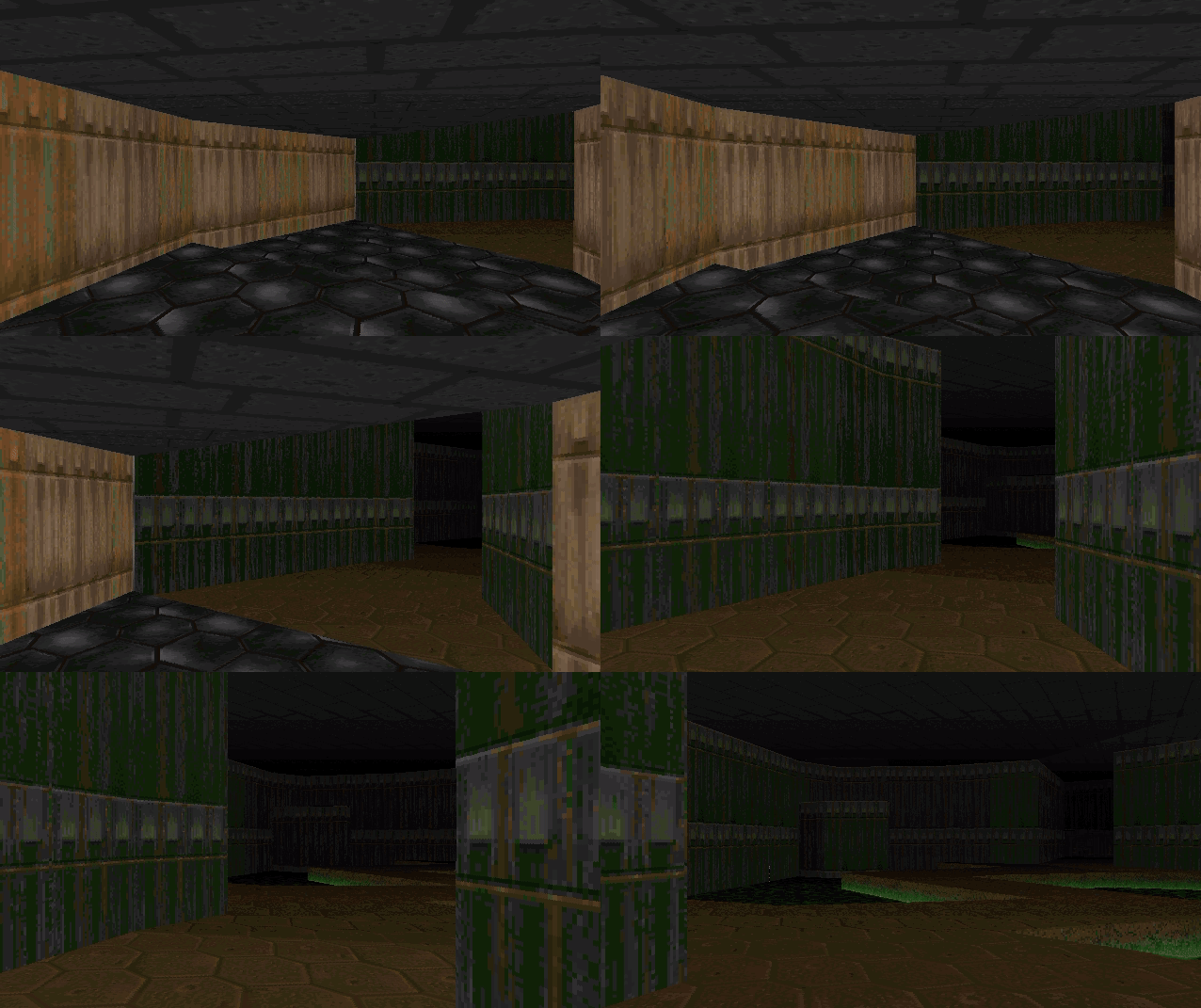
You may have noticed that these images get darker the further we’re looking. This is an intentional effect from DOOM that enhances the sense of depth.

This is easiest to see without the floor textures:

Conceptually, this is really simple. Render pixels darker when they are further away.

The light level of a pixel column drops off as the raycast distance increases. Or rather, the darkness level increases with the raycast distance.

Pixel values are written to the screen as RGB values. How does one take an RGB value and make it darker? Well, white is 0xFFFFFF and black is 0x000000, so the simplest way is to decrease each channel by some percentage. To do it “more correctly”, you can convert your RGB color into the Lab colorspace, reduce its lightness, and then convert it back. That is an expensive operation.

The original DOOM didn’t have access to RGB values. Or rather, it didn’t have access to all of them. According to the DOOM Black Book, PC video games of the 90s had 320×200 resolution with 1 byte per pixel drawn from a 256-color palette. This meant that programmers could set the 256 colors in the palette, and drawing a pixel to the screen effectively meant indexing into this palette by setting a 1-byte pixel index rather than a full RGB value.

So how does one change a pixel’s brightness?

The DOOM developers precomputed mappings from pixel values at full brightness to pixel values at reduced brightness. There were many such colormaps, 32 that were computed for all light levels from 100% brightness all the way down to 0%. There were even some additional colormaps, such as an inverted colormap used when the player becomes invulnerable:

All wall textures and flats store pixel indices rather than RGB values. These pixel indices pass through the chosen colormap and then index into the palette to get the RGB value. In the original DOOM system, indexing into the palette was done for you by the video card. I’ll be doing it myself here.

u8 palette_index = patch.post_data[column_offset];
palette_index = colormap.map[palette_index];
u32 abgr = *(u32*)(palette.colors + 3 * palette_index) | 0xFF000000;

The palette stores sequential BGR values, so we just grab the section we need and then overwrite the FF for the alpha channel.

struct Palette {
    u8 rgbs[768];
};

struct Colormap {
    u8 map[256];
};

As a final note, there is one additional lighting effect that helps make the map more legible. Like the trick used in Wolfenstein, walls closer to being x-aligned are drawn 1 point brighter than normal, and walls closer to being y-aligned are drawn 1 point darker than normal. Furthermore, each sector has its own baseline light level. This lets the map creator make some areas naturally darker, and allows for some nice floor shadow effects:

DOOM Levels

Ah, that last image gave it away. The geometry changes and lighting changes now bring us more-or-less to parity with the original DOOM. We can load and traverse the original DOOM levels!

This rendering is done using the raycasting method, via our DCEL, rather than using DOOM’s BSP. This means we can totally avoid loading SEGS, SSECTORS, NODES, and the BLOCKMAP.

E1M1 loaded into the TOOM editor.

Work was required to be able to load the geometry into our DCEL correctly. Mainly in being able to properly flip mesh edges in order to be able to produce edges that match the map geometry, and then constrain them. I might cover that in a future post.

Portals

Okay, we’ve reached geometric parity with DOOM. Is there something this DCEL approach can do that DOOM cannot?

So how does that work?

When we raycast or when the player walks around, we traverse between faces in our triangle mesh. We can create a portal by linking two edges in the triangle mesh and adding the necessary logic such that, when traversed, we come out the linked edge instead.

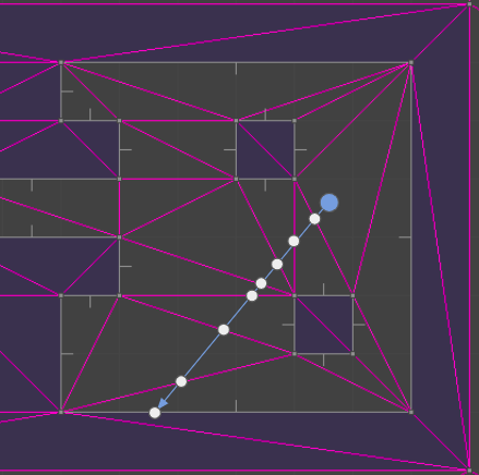
Below we see the top-down view of the portal setup playing out. The red triangle shows the player camera and its approximate view cone.

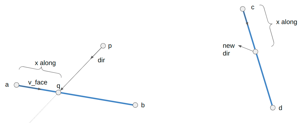
The player movement for when we traverse a portal is:

// Suppose we are crossing the line segment AB from pos to pos_next,
// where pos_next now lies on AB.
Vec2f v_face = b - a;

// Calculate where along the segment we intersected.
f32 v_face_len = Norm(v_face);
f32 x_along_texture = v_face_len - Norm(pos_next - a);

// Update our quarter edge using the destination quarter edge
// stored in the side info.
camera_state->qe = mesh.Tor(side_info->qe_portal);

// The vector along the new face is
Vec2f c = mesh.GetVertex(side_info->qe_portal);
Vec2f d = mesh.GetVertex(mesh.Sym(side_info->qe_portal));
Vec2f cd = d - c;
cd = Normalize(cd);

// Our new position is:
camera_state->pos = c + x_along_texture * cd;

f32 angle_ab = std::atan2(v_face.y, v_face.x);
f32 angle_cd = std::atan2(cd.y, cd.x);
f32 angle_rot = CounterClockwiseAngleDistance(angle_ab, angle_cd) + M_PI;
f32 cos_rot = std::cos(angle_rot);
f32 sin_rot = std::sin(angle_rot);

// Now to get the new direction, we need to rotate out of the new face
dir = {cos_rot * dir.x - sin_rot * dir.y,
       sin_rot * dir.x + cos_rot * dir.y};

// We also need to rotate our speed
vel = {cos_rot * vel.x - sin_rot * vel.y,
       sin_rot * vel.x + cos_rot * vel.y};

Geometrically, we are figuring out the rotation angle between our portals (which could be precomputed) and then rotating our movement direction and speed when we traverse.

Note that the +pi term compensates for the fact that the destination portal side is oriented 180 degrees with respect to the source portal side.

When we raycast through portals, we have properly account for any height changes on the receiving sector. We want to view the other side as if we were the appropriate height:

camera_z += (sector_dst->z_floor - sector_src->z_floor);

There is a bit of extra bookkeeping we have to do with portals – namely that for flats to render correctly we have to update the camera position to the place it would be as if the portal did not exist and we were peering toward our destination:

We then have to recompute some of the vectors used to create spans. This is all because flats are rendered on a fixed grid, and we compute where we are in that grid based on the camera location. We have to fake the camera being in the proper location “behind” where the portal surface is. Please take a look at the source code for the nitty-gritty.

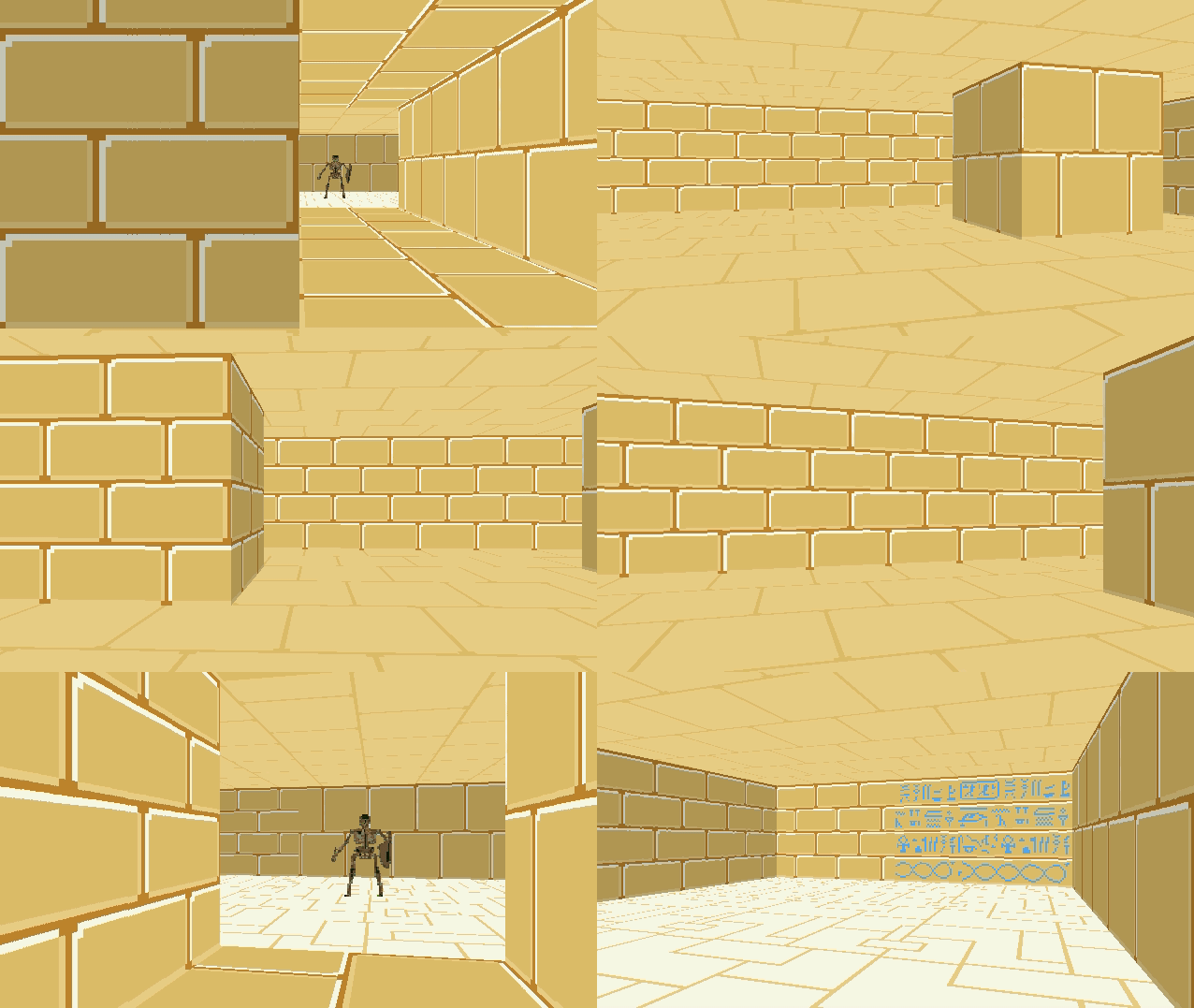
There is a lot of neat gamemap stuff that one can do with portals and the non-Euclidean geometry they unlock. Some of it is more blatant, like the first portal, and some of it can be quite subtle, like a hallways that is shorter or longer than expected.

Conclusion

This blog post covered adding variable z heights for floors and ceilings, which then required being able to render wall sections revealed at floor or ceiling height changes. We rendered those vertically, because that is most efficient. We then figured out a way to render horizontal textures too, which were most efficient to render in horizontal strips. We added some lighting effects. We then had everything we needed to represent the original DOOM level geometry. We concluded with an overview of portals – sides in our mesh that are linked together such that crossing one results in you exiting out the other.

I made the code for TOOM and TOOMED available in separate repos. TOOM is the “game”, written in pure C without graphics libraries. TOOMED is the TOOM Editor, written in C++. It basically doesn’t use graphics libraries either, but it does use Dear ImGui with an accelerated backend, as well as have more liberal data structures for easier manipulation of game data and assets.

That’s more or less it for TOOM, for now. There are a few things the renderer doesn’t support that DOOM has, such as animated nukage, pickups, or proper handling for partially-transparent walls. There obviously isn’t any gameplay. No shooting or doors or anything like that. Those things are neat, of course, but I feel like I already understand how they work, and it’d just be pretty tedious work for me to get TOOM running with all that. Maybe I’ll do it, but for now I’m thinking I’ll be turning to other interests. Thanks for reading!
A Note on Efficiency

One of the reasons that this TOOM project interested me in the first place was the promise that I might learn how to program something “for real” and really have to care about performance. I admire folks like Casey Muratori and Jonathan Blow who ardently advocate for efficient programming, and that software engineers should understand what goes on under modern abstractions.

I tried to keep TOOM running at over 30fps. I was able to track this using a profiling technique covered by Casey in his performance-aware programming class.

For a moderately-expensive scene in E1M1, TOOM clocks in at about 130fps:

Frame dt:   28.9459ms
Total time: 7.6722ms, 130.3 fps (CPU freq 1992267920)
  Poll:   32405 (0.21%)
  Tick:   7097 (0.05%)
  Render: 15245367 (99.74%)
  DKBS:   249 (0.00%)

As we can see, 99.74% of the time is spent rendering. That is to be expected, since that is where all the work is.

Here the frame dt is the 30Hz enforced by my monitor, because SDL is syncing to my monitor refresh rate. This is with a 640 x 320 window, which is double the resolution of the original DOOM. Yes, this is like 30 years after DOOM came out, but I am nevertheless quite happy with these results.

TOOMED, however, is a bit slower:

Total time: 35.2314ms (CPU freq 1991906430)
  GetRightHandedness  [ 25801]:     792837 (1.13%)
  RenderPatchColumn   [  1760]:    8381240 (11.94%)
  RenderSpan          [   318]:    3498674 (4.99%)
  Raycast             [   640]:   35425448 (50.48%, 72.23% w/children)
  Raycast_EdgeChecks  [  8600]:    2322161 (3.31%, 4.43% w/children)
  Raycast_WithValidSideInfo[  2720]:    3599229 (5.13%, 17.32% w/children)
  RenderScene         [     1]:     146851 (0.21%, 77.17% w/children)

It takes about 4.6x as long for TOOMED to render the same scene, giving it a frame rate of about 28fps. That is not great.

Yes, TOOMED is doing a little more, in that it also renders the top-down GUI. However, that GUI stuff is pretty negligible. I believe the real culprit here more-or-less boils down to two things: memory layout and dictionary lookups.

In TOOM, everything is accessed directly in the binary save file. Entries are all nicely indexed and can be quickly accessed. In TOOMED, since we’re editing things, we store them in std::vectors and std::maps, which results in disparate structures spread out in different locations. In many cases it simply takes more effort for the CPU to get access to what it needs. Furthermore, dictionary lookups, while being O(1), are still doing more work than a simple array access. The delta here, 4.6x, is pretty substantial, and this is the sort of takeaway that I think serious gamedev folk mean when they say paying attention to your data structures and memory strategies matters.

As a final fun learning point, my raycast method was initially recursive. That is, every time we step our ray and transfer over a triangle edge, I’d recurse down in order to process the next triangle step. I figured that this would make it easier to later back-track and render things like monsters or item pickups. However, TOOMED was running _extremely_ slowly, around 70ms per frame. Changing from recursion to a loop cut that time in about half. Its the same amount of work, theoretically, only now we don’t have to make a bunch of copies every time we push to the stack.

Taking TOOM Off-Grid, without BSPs

I’ve continued tinkering with my little C software renderer covered in previous blog posts. So far we’ve rendered a blocky, textured environment reminiscent of Wolfenstein 3D:

You’ll notice from the window header that the project is called TOOM, as in, Tim DOOM. It isn’t Timenstein 3D, so we have some work to do.

In this blog post we’ll go off-grid and move to general 2D geometry.

Binary Space Partitioning

John Carmack’s great innovation in creating DOOM, the design change that made rendering general 2D geometry in a constrained computing environment possible, was the BSP tree. BSP trees make it efficient to walk over the surfaces in your world in a front-to-back order, based on the camera location.

Each node in the tree represents a splitting plane (or line, rather, as this is 2D) that subdivides the level. All faces below that node lie entirely on one or the other side of that dividing line. At the bottom of the tree you get leaf nodes, which each represent a single convex map region:

DOOM’s E1M1 map, image from the doomwiki

While the BSP tree is a genius addition, it does come with its disadvantages. The main one being its construction. For DOOM this meant running Node Builder after level design, a process that does a lot of iteration to find the best splitting planes for a well-balanced tree. Not only does this take a while, it also requires the level geometry to remain static. This means no 2D geometry changes. (DOOM’s doors all move vertically).

I kind of want to be able to support geometry changes. Plus, I kind of like the idea of figuring out something different. So, we’re going to take another approach.

Keep on Raycasting

In Wolfenstein Raycasting in C, we talked about how the software renderer casts rays out into the world for every pixel column in the screen:

This raycasting was fairly efficient because we limited our geometry to a regular grid:

Now, we’re going to do the exact same thing, except on a triangle mesh:

Moving to a triangle mesh has several consequences. On the plus side, it supports general 2D geometry, so we no longer have to constrain ourselves to a grid of blocks. We can fairly easily move vertices and mutate our environment. On the other hand, casting a ray through a set of triangles tends to be more computationally expensive, we have to develop and maintain a more complicated data structure, and we aren’t entirely free to mutate our environment – our triangles have to remain valid (right-handed).

It isn’t 1993 anymore, so I’m hoping that the performance hit from raycasting on a mesh isn’t too bad on a modern processor. I’ve already been tinkering with triangle meshes, so I’m eager to adapt what I learned there to this new application. I also think we can overcome the editing limitations.

Below is a GIF from TOOM. The left half of the image is rendered with the new triangle meshes. The right half of the image is rendered with the old blocky technique. (The new map was made to be identical to the old one, for now). The textures assigned to the walls aren’t the same just yet, so you can see a fairly clear division.

The debug view gives us a better sense of what is going on:

Raycasting through triangles is the same, conceptually, as raycasting through a grid. We keep casting through cells until we reach a solid cell. Now, instead of square cells with regular spacing, we have arbitrarily-sized, triangular cells.

Each raycast starts with a ray at the camera location \(\boldsymbol{p}\) heading in a direction \(\hat{\boldsymbol{d}}\). As we iterate \(\boldsymbol{p}\) will be shifted out into the world. In the first iteration, \(\boldsymbol{p}\) will be the camera location and can lie inside a triangle face. In future iterations, \(\boldsymbol{p}\) is lies on an edge that we crossed in the previous iteration.

We take the three bounding vertices \(\boldsymbol{a}\), \(\boldsymbol{b}\), and \(\boldsymbol{c}\) and intersect the line through \(\boldsymbol{p}\) with the direction \(\hat{\boldsymbol{d}}\) with AB, BC, and CA, representing each intersection point as \(\boldsymbol{p}’ = \boldsymbol{p} + t \hat{\boldsymbol{d}}\). We step forward to the edge that we hit first. That is, the edge for which \(t\) is smallest (but positive). We ignore any edge we are already on.

We start by computing \(\boldsymbol{q}\), a point far enough along \(\boldsymbol{d}\) that it should exit the triangle:

Before we calculate an intercept, we can disregard checking an edge EF if the triangle EFQ is not left-handed. This helps us avoid cases where an intersection will either never occur or lie behind our ray. For example, we can skip checking AB because ABQ is right-handed (counter-clockwise):

We should check BC, because the triangle BCQ is left-handed (clockwise):

We can now calculate the interection point’s \(t\)-value. For the edge BC, this is:

\[t_{BC} = \frac{(\boldsymbol{c}-\boldsymbol{b}) \times (\boldsymbol{p}-\boldsymbol{b})}{(\boldsymbol{q}-\boldsymbol{p}) \times (\boldsymbol{c}-\boldsymbol{b})}\]

In code, this works out to:

if (GetRightHandedness(b, c, q) < -eps) {
   // We would cross BC
   v2 v = c - b;
   v2 w = p - b;
   f32 t_bc = cross(v, w) / cross(q - p, v);
   if (t_bc < t_min) {
      t_min = t_bc;
      qe_side = qe_bc;
      v_face = v;
   }
}

We just repeat this block three times, once for each edge. Each time we get an intersection, we keep it if it is earlier than any previous intersection. When we do, we also store the edge that we pass over (via its quarter edge in the DCEL).

Just like before, we propagate our point \(\boldsymbol{p}\) up to the new edge and then either iterate again if the new face is empty, or break out if the new face is solid.

We do have to make some minor modifications in how we access the face texture. With the grid we could safely assume that every wall was square, with a corresponding 64×64 pixel texture. Now walls can have arbitrary aspect ratios, so we have to do a tiny bit of math to index into the texture based on our intersection location along the edge:

f32 PIX_PER_DISTANCE = TEXTURE_SIZE / TILE_WIDTH;
QuarterEdge *qe_face_src = qe_dual->rot->rot->rot;
f32 x_along_texture = length(v_face) - length(pos - qe_face_src->vertex);
u32 texture_x = (int)(PIX_PER_DISTANCE * x_along_texture) % TEXTURE_SIZE;

Collision Detection

One immediate advantage of using the DCEL is that we can leverage it for collision detection. In DOOM, collision detection is done via a blockmap, which is just a discrete 128×128 pixel grid. Each grid cell stores the lines in that block. An entity moving in a cell can just check for collision against all of the lines in the cell. The blockmap is constructed on level export, and again assumes static 2D geometry.

We don’t have to use a bockmap, because we have the DCEL. We can simply store the face that our player is in and check for collisions every time we move them. Our player movement code is the same as the player movement code in this previous blog post. Any time we would cross over a solid edge between two faces, we simply move up to the edge instead, and lose any velocity into the edge.

The current approach assumes the player is a single point. If we want, we can create a second collision mesh that uses inflated solid geometry to compensate for the player’s collision volume. We would have to keep that second mesh synchronized with any changes to the geometry mesh.

DCELs make pathing and shooting computations easy too. DCELs are primarily used in games for pathing (via Nav Meshes) and collision checking for a gunshot is just a raycast where we also care about intersections with enemies.

Game Map Representation

The biggest difference here was not so much the rendering code, but more the integration of the mesh data structure and how we represent the game map. With the Wolfenstein-style renderer we were able to represent the map using 2D arrays:

tiles = UInt8[
    1 1 1 1 1 1 1 1 2 1 1 1 2;
    1 0 0 0 0 0 0 1 2 0 0 0 2;
    1 0 0 3 0 0 2 2 2 0 0 0 2;
    1 0 0 0 0 0 0 0 0 0 0 0 2;
    1 0 0 0 0 0 2 2 2 0 0 0 2;
    1 0 2 0 0 0 0 1 2 0 0 0 2;
    1 0 0 0 0 0 0 1 2 0 0 0 2;
    1 1 1 1 1 1 1 1 2 3 3 3 2]

floor = UInt8[
    1 1 1 1 1 1 1 1 2 1 1 1 2;
    1 4 4 4 4 4 4 1 2 5 5 5 2;
    1 4 4 3 4 4 2 2 2 5 5 5 2;
    1 4 4 4 4 4 2 2 2 5 5 5 2;
    1 4 4 4 4 4 2 2 2 5 5 5 2;
    1 4 2 4 4 4 4 1 2 5 5 5 2;
    1 4 4 4 4 4 4 1 2 5 5 5 2;
    1 1 1 1 1 1 1 1 2 3 3 3 2]

ceiling = UInt8[
    1 1 1 1 1 1 1 1 2 1 1 1 2;
    1 4 4 4 4 4 4 1 2 4 4 4 2;
    1 4 4 3 4 4 2 2 2 4 4 4 2;
    1 4 4 4 4 4 2 2 2 4 4 4 2;
    1 4 4 4 4 4 2 2 2 4 4 4 2;
    1 4 2 4 4 4 4 1 2 4 4 4 2;
    1 4 4 4 4 4 4 1 2 4 4 4 2;
    1 1 1 1 1 1 1 1 2 3 3 3 2]

Each cell could thus be marked as solid or not depending on whether the cell’s entry in tiles is 0. Nonzero values corresponded to texture indices. Similar arrays were used for the floor and ceiling textures.

With the general 2D geometry, we no longer have a convenient text short-hand. The DCEL has a lot of pointers and is no fun to edit manually. We have to store all vertices, quarter edges, and the associations between them. We then optionally mark edges as being solid, and when we do, set edge texture information.

At this point the game map consists of two things:

  • a triangle mesh
  • optional side information

My representation for side information is pretty simple. It is just a structure with some flags, a texture id, texture x and y offsets, and the associated quarter edge:

// The information associated with one side of an edge between vertices in 
// the map. If this represents the directed edge A->B, then it describes the
// edge viewed on the right side of A->B.
struct SideInfo {
    u16 flags;
    u16 texture_id;
    i16 x_offset;
    i16 y_offset;
    QuarterEdgeIndex qe;
};

The map data is packed into the binary assets blob (similar to a DOOM WAD file) and loaded by the game at start.

Editing this game data is rather hard to do by hand, so I started working on an editor on the side. The editor is written in C++, and I allow myself the use of whatever libraries I want. I might go over that in more detail in a future post, but for now I just want to show how it can be used to adjust the map:

The gif here is fairly large. It may have to be viewed separately.

Having an editors gives us a place to put supporting code and lets us use more convenient data structures that aren’t streamlined for the C software renderer. The editor can then do the lifting required to export our game data into the form expected by the game.

Conclusion

The TOOM source code for this post is available here. I have been overwriting my assets file, and the new ones are no longer compatible, so unfortunately do not have a good assets file to share.

In this post we took our blocky Wolfenstein-style environment and moved to general 2D geometry. We didn’t follow DOOM and use a BSP, but instead stuck with raycasting and used a DCEL.

What we have now is much closer to DOOM, but still lacks a few things. Geometrically, we don’t have variable floor heights, which means we also don’t yet worry about wall surfaces between variable floor heights. We also aren’t animating doors or elevators, and we don’t have textures with transparency. We aren’t doing any lighting, other than manually setting some faces to be darker. DOOM really was groundbreaking.

A Handcrafted Wedding

I’m now married!

We had a wonderful wedding, with loving friends and family members, many of which traveled pretty far to celebrate with us. It was a pretty small wedding, but it was a heartfelt one, and we put a lot of effort into things to make it the wedding we dreamed of. In this blog post I’ll cover some of the personal touches we were able to add.

TikZ Place Cards

Photo by @wendyandgeorgephoto

We had guests RSVP via a Google form, which asked them information like their name, which meal they wanted, and whether they had any food allergies. This produces a Google sheet, which I exported to CSV and loaded into a little Julia notebook. My notebook then typeset place cards for each guest, displaying their name, table assignment, meal choice, and any food allergies. This used TikZ via TikzPictures.jl, and inverted each image in order to get a fold-able card:

The script did some basic layout to produce paper sheets with multiple cards such that we could print them out with maximum effectiveness:

We had to address some corner cases, such as babies (which don’t have meals), guests with multiple allergies, and guests with long names.

We used the same approach to make a few other place cards for things like the desserts table:

Table Numbers

Each dining table had a number, and we needed a way to indicate which table was which. My partner had a fantastic idea, and made table signs with table numbers that included photos of us at that age. So, table 2 had photos of each of us at 2 years of age, table 3 had each of us at 3 years of age, etc:

Photo by @wendyandgeorgephoto

These were made in Keynote, and were printed out on photo paper and cut out by hand.

Succulent Centerpieces

We also wanted table centerpieces, but balked at the extreme price of floral arrangements. Again, my partner had a fantastic idea. She had been learning pottery, and decided that she would throw her own bowls, glaze and fire them, and then make succulent arrangements. She gradually worked on these bowls all year, learning to make bigger and better bowls as she progressed, and made some very beautiful works of art. Many of the succulents were clippings from my mom’s garden. The end result was amazing!
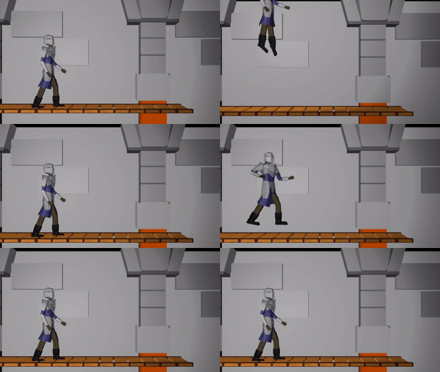
Photo by @wendyandgeorgephoto

Portable Piano

We wanted our best man to play the piano during the ceremony. The only problem was that we had to use a portable piano that wasn’t plugged into an electrical outlet.

Thankfully, we were able to use the best man’s electric keyboard, but said electric keyboard had to be modified to use a portable power source. After getting on YouTube, including watching a delightful video of a man playing music outdoors, we determined that building a battery was pretty straightforward. The piano takes 12v, so I ordered a 12v, 20 Ah battery.

The battery life in hours is its capacity (in amp-hours) divided by the current draw (in amps). The current draw is watts / volts, which for us is around 40 W / 12 v ~ 3.33 amps. Thus we expect the piano to last 20 Ah / 3.33 A ~ 6 hours. We figured that should be more than plenty.

I also ordered a charger, and a Yamaha piano wall wart. I cut the plug off of the wall wart and connected that, plus a fuse, to the battery:

(with lots of protective electric tape – don’t want to get shocked.)

We put the battery in the cardboard box it came in, spray painted it black, and 3d-printed a nice little cover:

We additionally 3d-printed a little wedge so that the battery could sit on the X-frame stand that supports the piano. Unfortunately, I forgot to get a photo of that.

And then there was the problem that the piano was initially dead after we borrowed it. After much troubleshooting, my partner’s internet investigations suggested that we replace one particular capacitor that was known to wear out on this brand of electric keyboard. So (with permission) we ordered it, took the piano apart, and replaced the capacitor.

Ring Box

We used the 3d printer for other things as well! My partner printed a wonderful ring box whose design she found:

Photo by @wendyandgeorgephoto

Our names are inlaid on the other side.

Homemade Desserts

You know what’s harder than making desserts for your own wedding? Transporting them to the wedding.

Enter – the Macaron Transport Vehicle (MTV). My partner is fantastic at baking macarons, and has spent something like 10 years perfecting the recipes. She baked the macarons, and also came up with the method for getting them to the venue.

Each MTV consisted of an Ikea cooler bag with a cooler-bag-bottom-sized ice pack. This could be loaded with trays of macarons, with 3d-printed spacers to allow for tray stacking. The macarons made it safe and sound, and cold!

Photo by @wendyandgeorgephoto

Making the macarons was a 3-day process. The fillings were made on Day 1, the shells on Day 2, and they were assembled on Day 3.

Wedding Favors

We wanted to have something for our guests to take home with them. We thought about giving out succulents, but figured those would be hard to travel with, and maybe guests wouldn’t want them. We figured that pretty much everyone likes chocolate.

There are services that let you make your own custom chocolate wrappers. We tried a sample or two and weren’t really blown away by the chocolate itself. So we decided to just buy chocolate bars that we liked and make our own basic sleeves:

These were made in Keynote, and were printed on heavier paper.

Funny story about the text on the back. I initially wrote something much longer, and my partner had the great idea to use ChatGPT to consolidate it a bit. It worked really well, with some minor manual adjustments.

We then tried asking it to add some chocolate puns. ChatGPT 3.5 was decidedly terrible at adding puns. It basically just inserted “choco” into the text in random places. Ah, well.

Website

Lastly, rather than use a wedding website service, I figured I had my own website already, and could just add to that. It was just a simple page based on the same HTML5 Up template that I use for my main website today. Per a friend’s suggestion, I used Leaflet and Open Street Maps to display the location of the venue and the hotel. This was also the page that guests could access the RSVP Google Form from.

Conclusion

We had a wonderful wedding, with wonderful guests and a lot of wholesome, positive energy. Things went incredibly smoothly, and the worst thing about it was how quickly it all flew by.

I think the little touches that we added made the wedding feel more personal.

Billboard Sprites

I’m still on a Wolfenstein 3D kick, so this month we’re going to further extend the software render. We’re doing it in C and are manually setting individual pixels (no 3D lib). As before, I’m deriving this myself, so while we should end up with something similar to Wolfenstein 3D, things are probably not going to be a perfect match.

The last post left us with a textured blocky world. I felt like the next thing to do was to be able to populate that world.

Wolfenstein 3D (and DOOM) were before the time of 3d meshes. Enemies and set pieces (like barrels) were rendered as flat images. These billboard sprites always face the camera, since that simplifies the rendering math:

In Wolfenstein 3d, all wall textures are 64×64 images. They kept things simple and made all sprites 64×64 images as well. Unlike wall textures which were always solid, sprites have a bunch of fully transparent pixels. This was indicated using magenta.

Behold my fantastic programmer art:

We can load this image in like we do with our wall textures. Now we just have to figure out how to render it.

Render Math

Each entity has a position in 3D space. First we transform the object’s location in game space to a camera-relative space:

We can do this with:

\[ \begin{bmatrix} e’_x \\ e’_y \end{bmatrix} = \begin{bmatrix} \hphantom{-}\cos \theta & \sin \theta \\ -\sin \theta & \cos \theta \end{bmatrix} \begin{bmatrix} e_x – c_x \\ e_y – c_y \end{bmatrix} \]

We can skip rendering the entity at this point if it is behind the camera (\(e’_x < 0\)).

Next we calculate its extents in the screen’s horizontal dimension:

The billboard’s width is the same as the tile width. We can do some math to get the camera x-pixel locations:

\[\begin{aligned} x_\text{lo} = \left(\frac{1}{2} – \frac{e’_y + w_\text{sprite}/2}{e’_x \, \text{fov}_x}\right) \text{screenpix}_x \\ x_\text{hi} = \left(\frac{1}{2} – \frac{e’_y – w_\text{sprite}/2}{e’_x \, \text{fov}_x}\right) \text{screenpix}_x \end{aligned}\]

We’re just moving half the sprite width in either direction, then dividing by the screen’s width at the entity’s location. We have to flip about 0.5 because pixels go left to right in screen space, and then scale up by the number of pixels.

The image’s height is determined by the distance the entity is from the camera. The calculation is the same one we used for determining the height of walls. This gives us \(y_\text{lo}\) and \(y_\text{hi}\).

Now we can iterate from \(x_\text{lo}\) to \(x_\text{hi}\) in 1-pixel increments, rendering each column of pixels as we go between \(y_\text{lo}\) and \(y_\text{hi}\). For every \(x\)-increment of 1 pixel we move \(64 / (x_\text{hi} – x_\text{lo})\) pixels horizontally in the sprite image. Similarly, for every \(y\)-increment of 1 pixel we move \(64 / (y_\text{hi} – y_\text{lo})\) pixels vertically in the sprite image.

This gives us a billboard sprite in the correct location that scales as we move closer or farther away. Unfortunately, we’re rendering the magenta pixels and we’re drawing over walls that should be blocking our view.

We can trivially skip rendering magenta pixels with an if statement.

Fixing the wall occlusions also turns out to be pretty simple. We are rendering the entity after we render the walls. When we render the walls we have to calculate the raycast distance. We keep track of this distance for each pixel column, and only render a given entity pixel column when it is closer to the camera.

So there we have it – billboard sprites with occlusions. We first render the floors and ceilings, we then render the walls, and we then finally render all entity sprites.

DOOM Sprites

Unfortunately, my programmer art is pretty terrible. It works okay for the walls, ceilings, and floors, but it doesn’t work so well for entities.

I considered using Wolfenstein 3D sprites, but I don’t want to go with the Nazi theme. I decided to go with DOOM sprites since the assets are easily available (and have been used by modders for decades).

We have to do some work to load from the DOOM assets (stored in a WAD file). I was surprised to find that the WAD format is quite similar to the asset format I made up that I was already using. They both consist of a header, followed by a series of blobs, terminated with a table of contents. We can just load the whole thing into memory and then point to the data we need.

Wolfenstein 3D stored everything in 64×64 images. DOOM was a bigger project, with things of different sizes, and so went for a more compressed format (at the expense of added complexity). Sprites are stored as patches, which slice the image up by pixel column, and only specify continuous pixel column regions that should be drawn (ignoring transparent pixels).

We don’t have to waste any space on transparent columns:

Many columns simply consist of a single continuous range of pixels:

Some columns have several pixel intervals:

Each patch has a header defining its width and height, and its position relative to the entity’s origin. (If a monster has an arm stretched out to the left, we want to know to offset the image to the left a bit). This is followed by byte offsets to pixel data. One of the cool things here is that if two pixel columns happen to be the same, we don’t have to store them twice, but can just point to the same data.

Pixel columns are each a sequence of pixel intervals with a given offset from vertical, some number of pixels, and then the pixel values. We know we’ve reached the end when the vertical offset is 0xFF.

DOOM is restricted to a 256-color palette. The pixel data in each patch stores 1-byte indices into this palette. When rendering, we take the index and look up the appropriate color. (DOOM also has a colormap that it uses to darken things further from the camera, but I’m not doing that quite yet).

While DOOM does use billboard sprites, they also rendered each frame from 8 different viewing angles. We can determine which sprite to use for a given frame based on our viewing angle:

f32 monster_heading_rel = 
                 fmod(monster_heading+camera_heading+PI+PI/8.0,2*PI);
int monster_frame = (int)(monster_heading_rel * 8.0/(2.0*PI)) & 0x07;

This gives us some nice visual continuity as we walk around the monster:

Conclusion

The code for this post is available here. The zip file contains my assets, but you’ll have to separately find the DOOM assets, since I didn’t think it’s okay to host them myself. Thank you DOOM team for making those available!

I ended up splitting my source code into multiple files, since the code was steadily growing and becoming less manageable. You’ll notice that I use fewer static functions and I pass in the objects that I use instead.

The code now generates a second window, in which I render a top-down debug view. I allow myself to use SDL_RenderDrawLine and SDL_RenderFillRect here. (They’d be pretty easy to implement myself, but whatever).

I’m not sure how far I’ll take this project. It certainly has been fun so far! Fully fleshed games are pretty involved, and as we’ve seen I am pretty limited when it comes to asset creation. I do have a neat idea that I want to try out with respect to more general 3D rendering and collision detection, and I kind of want to have some rudimentary monster fighting interactions. We’ll see.

Textures for Wolfenstein

In the previous post we derived raycasting for a game in the style of Wolfenstein 3D. That is, a blocky game world with a regular grid and with the player’s view restricted to looking out horizontally. These restrictions let us simplify rendering significantly. At the end of the last post we were drawing colored blocks by casting a ray out into the world for every pixel column, and drawing the appropriate color after some geometry based on the distance the ray traveled before hitting the wall:

This gave us frames that consisted of solid floor and ceiling colors, and solid wall colors for boxes:

In this post we’ll add some textures. As before, this is all in C.

Wall Textures

We’ve already done most of the work required to render walls. Now, rather than drawing a column of pixels in a solid wall color, we’re instead going to render a column of pixels based on a wall texture.

After we’ve done the raycasting, we have our distance to the wall that we intersect and we have calculated the y-interval on the screen for the column of pixels we need to draw the wall in. In order to texture that wall, we need to find the corresponding column of pixels in the texture for that wall and render it into that column:

In Wolfenstein 3D, all textures are 64 x 64 pixels. This uniformity simplifies the problem.

We have the collision location after intersecting with our world geometry. This collision location is decomposed into a block index (x and y) and the remainder \((x_\text{ref}, y_\text{ref})\) – the position within that tile:

In this case, our tiles have width 1.0, to keep things simple. The world coordinate (3.152,1.000) is decomposed into tile indices (3,0) to give us the blue wall tile that we hit, and remainders (0.152, 1.000) to tell us where within the tile we hit. Because we always intersect at a point on the grid lines, one of our remainders is always either zero or one.

In this case, we use the \(x\) remainder to map into our texture. We’re viewing the texture from the north, so \(x_\text{rem} = 0.0\) corresponds to \(x_\text{texture} = 63\), and \(x_\text{rem} = 1.0\) corresponds to \(x_\text{texture} = 0.0\). The mapping in between is linear:

\[x_\text{texture} = 64 \frac{w_\text{tile} – x_\text{rem}}{w_\text{tile}}\]

The remainder we use, and whether we invert it, depends on the north/south/east/west direction the wall is facing. We can get this information from our decomposed coordinate:

f32 rem = 0.0f;
if (dx_ind == 0) {
   rem = dy_ind < 0 ? TILE_WIDTH - x_rem : x_rem;
} else {
   rem = dx_ind < 0 ? y_rem : TILE_WIDTH - y_rem;
}
u32 texture_x = min((int)(TEXTURE_SIZE*rem/TILE_WIDTH),TEXTURE_SIZE-1);

We have to cast \(x_\text{texture}\) to an integer to get our pixel index, and ‘and’ it by 64-1 to prevent accidental bounds issues.

Now that we have located our texture pixel column, we need to scan vertically through the screen’s pixel column and identify the corresponding pixel \(y\) positions in the texture as we go:

The pixel column on the screen is bounded between \(y_\text{hi}\) and \(y_\text{lo}\). The texture is a matrix, and so the \(y\) coordinate increases down the texture. Thus, our mapping is:

\[\begin{aligned} y = y_\text{hi} & \mapsto y_\text{texture} = 0 \\ y = y_\text{lo} & \mapsto y_\text{texture} = 63 \end{aligned}\]

with a linear mapping in between:

\[y_\text{texture} = 64 \frac{y_\text{hi} – y}{y_\text{hi} – y_\text{lo}} \]

(Note that we use 64 rather than 63 since we’ll be flooring this when we code it).

Our column-rendering code is thus:

u32 denom = max(1, y_hi - y_lo);
int y_lo_capped = max(y_lo, 0);
int y_hi_capped = min(y_hi, SCREEN_SIZE_Y-1);
for (int y = y_hi_capped; y >= y_lo_capped; y--) {
   u32 texture_y = (y_hi - y) * TEXTURE_SIZE / denom;
   u32 pixel_index = texture_y + texture_x*bitmap->n_pixels_per_column;
   u32 color = BITMAP_WALL.abgr[pixel_index];
   state.pixels[(y * SCREEN_SIZE_X) + x] = color;
}

We can make a slight optimization by factoring out the column lookup, and just increasing our pixel baseline:

u32 baseline = texture_y + texture_x*bitmap->n_pixels_per_column;
u32 denom = max(1, y_hi - y_lo);
int y_lo_capped = max(y_lo, 0);
int y_hi_capped = min(y_hi, SCREEN_SIZE_Y-1);
for (int y = y_hi_capped; y >= y_lo_capped; y--) {
   u32 texture_y = (y_hi - y) * TEXTURE_SIZE / denom;
   u32 color = BITMAP_WALL.abgr[texture_y+baseline];
   state.pixels[(y * SCREEN_SIZE_X) + x] = color;
}

We can calculate how many \(y\)-pixels to step every frame, and just use that instead:

u32 baseline = texture_y + texture_x*bitmap->n_pixels_per_column;
u32 denom = max(1, y_hi - y_lo);
f32 y_loc = (f32)((y_hi - y_hi_capped) * TEXTURE_SIZE) / denom;
f32 y_step = (f32)(TEXTURE_SIZE) / denom;
for (int y = y_hi_capped; y >= y_lo_capped; y--) {
   u32 texture_y = min((u32) (y_loc), TEXTURE_SIZE-1);
   u32 color = BITMAP_WALL.abgr[texture_y+baseline];
   state.pixels[(y * SCREEN_SIZE_X) + x] = color;
   y_loc += y_step;
}

This give us some nice texturing:

We can introduce a shading effect (also done in Wolfenstein 3D), by having different textures for north/south faces than east/west faces. I just have darkened copies of every texture. This makes the walls pop more, and subtly adds to the feeling of 3d immersion:

Speaking of multiple textures, let’s go ahead and do that:

How do we achieve this? Well, first, rather than having a single 64 x 64 pixel texture, here I am using a sheet of textures:

Right now this sheet has 2 columns, one for the lighter faces and one for the darker faces. It also currently has 3 wall types. To use a particular texture, we thus need to know its y index and whether it is light or dark. The wall type is based on the block type, which we store in our map data. We then apply a multiple of TEXTURE_WIDTH in the x and y directions when accessing this larger image:

u32 texture_x_offset = dx_ind == 0 ? 0 : TEXTURE_SIZE;
u32 texture_y_offset = (GetMapDataAt(x_ind,y_ind) - 1) * TEXTURE_SIZE;

Aside – Precompiled Texture Scans

I bought Fabien Sanglard’s Little Black Book on Wolfenstein 3D since writing the last post. It is a great overview of the original game, both technically and holistically. Now, the code written there looks and feels very different than the code we’re writing here, mainly because of the large differences in the hardware. Large parts of the book are about explaining how Wolfenstein 3D handled interrupts, was able to pipe pixel data through the VGA interface, and how fixed point arithmetic is used throughout the game’s logic.

I had a vague idea going into this project that the primary achievement behind Wolfenstein 3D was its raycasting engine. Yes, the raycasting engine was a breakthrough, but it is quite a small aspect in between myriad other engineering tricks that had to be pulled to get the game to run at a playable framerate back in the day.

One of the book’s tricks had to do with the texture column drawing code we just covered. Namely, this loop here:

for (int y = y_hi_capped; y >= y_lo_capped; y--) {
   u32 texture_y = min((u32) (y_loc), TEXTURE_SIZE-1);
   u32 color = BITMAP_WALL.abgr[texture_y+baseline]
   state.pixels[(y * SCREEN_SIZE_X) + x] = color;
   y_loc += y_step;
}

John Carmack (I’m assuming) had figured out a more efficient way to draw these pixel columns. In short, the machine code for these loops were precompiled for specific cases, and the renderer would just call the appropriate case. This would avoid all of the bookkeeping and for-loop if statements.

I learned that Wolfenstein 3D had hard-coded the player height to 1/2 the wall height, so y_lo_capped = y_hi_capped and y_lo = y_hi, always. This somewhat simplifies things. They could then precompile a loop based on the number of pixels in the column (which is 2*y_lo_capped). For example, if the column has height 2 (for a very distant wall), the precompiled function would be:

void draw_wall_2pix(
  uint32* screen_pixels,
  uint32* texture_pixels,
  uint32 screen_baseline,
  uint32 texture_baseline,
  ) {
  screen_pixels[screen_baseline++] = texture_pixels[texture_baseline];
  screen_pixels[screen_baseline++] = texture_pixels[texture_baseline+63];
}

Or, for 4 pixels:

void draw_wall_4pix(
  uint32* screen_pixels,
  uint32* texture_pixels,
  uint32 screen_baseline,
  uint32 texture_baseline,
  ) {
  screen_pixels[screen_baseline++] = texture_pixels[texture_baseline];
  screen_pixels[screen_baseline++] = texture_pixels[texture_baseline+16];
  screen_pixels[screen_baseline++] = texture_pixels[texture_baseline+32];
  screen_pixels[screen_baseline++] = texture_pixels[texture_baseline+63];
}

I thought that was a pretty neat trick. Sure, these precompiled functions take up space. (If I recall correctly, they generated one of these for every pixel column that was a multiple of 2, and used the closest). Drawing pixels is what the game is spending most of its time doing, so it makes sense to optimize. At least, it did back then. Right now I have no trouble hitting 60 Hz, so I don’t (yet) have to do this. (I’m also don’t have a full game – just some basic texture rendering).

Floor and Ceiling Textures

Wolfenstein 3D did not have floor and ceiling textures. Instead, it just filled them in with solid colors. In fact, it actually just filled in the floor and ceiling first and then drew the walls over that afterwards.

Ceiling and wall textures are similar to walls, we just have to work out the math again:

Here we have a ray cast through a pixel above the center of the screen such that it eventually hits the ceiling. The horizontal distance that the ray travels is \(r\), but the actual ray length is \(\ell\). From triangle similarity we get the same relation we used when working on walls in the previous post:

\[\frac{z”}{r”} = \frac{H-z}{r} \qquad \mapsto \qquad r = \frac{H-z}{z”} r”\]

We can calculate \(z”\) for a given pixel by calculating it from the pixel’s \(y\) index:

\[z” = \frac{y\, – \frac{1}{2}n_y}{n_y} h_\text{camera} \]

where \(n_y\) is the number of pixels in our screen’s y dimension, and \(h_\text{camera}\) is the camera’s physical height in world dimensions (a parameter we choose and can vary).

We’ve been using \(r” = 1\) for horizontal raycasting. Unfortunately, that’s only right when we cast a ray directly in the direction the player is facing. We have to adjust this by a small factor based on how far our pixel’s \(x\)-location is off from the screen’s center:

\[r” = \sqrt{1 + x_\delta^2}, \qquad x_\delta = \frac{x – \frac{1}{2}n_x}{n_x} w_\text{camera}\]

where \(n_x\) is the number of pixels in our screen’s x dimension and \(w_\text{camera}\) is the camera’s physical width in world dimensions (It should be related to \(n_y\) by our screen’s aspect ratio).

Knowing these, we can calculate the horizontal radius using the first equation:

int x, y; // pixel x and y coordinates, y > SCREEN_SIZE_Y/2
f32 x_delta = (x-SCREEN_SIZE_X/2.0f)/SCREEN_SIZE_X*state.camera_width; 
f32 rpp = sqrt(1.0f + x_delta*x_delta);
f32 zpp = (y-(SCREEN_SIZE_Y/2.0f))*(state.camera_height/SCREEN_SIZE_Y);
f32 r = (WALL_HEIGHT - state.camera_z)*rpp/zpp;

The horizontal location where we intersect with the ceiling is simply \(r\) in the direction through the screen’s pixel relative to the camera’s direction. If the direction the camera is facing is \(\boldsymbol{\hat{b}}\), and \(\texttt{rotr}(\boldsymbol{\hat{b}})\) is the right-hand 90-degree rotated camera direction, then the horizontal raycast direction \(\boldsymbol{\hat{d}}\) is:

\[\begin{aligned} \boldsymbol{\hat{d}} &= \texttt{normalize}( \boldsymbol{\hat{b}} + x_\delta \texttt{rotr}(\boldsymbol{\hat{b}}) ) \\ &= \frac{1}{\sqrt{1 + x_\delta^2}} \left(\boldsymbol{\hat{b}} + x_\delta \texttt{rotr}(\boldsymbol{\hat{b}}\right) \\ &= \frac{1}{r”} \left(\boldsymbol{\hat{b}} + x_\delta \texttt{rotr}(\boldsymbol{\hat{b}}\right) \end{aligned}\]

This makes the horizontal 2D intersection point:

\[\begin{aligned} \boldsymbol{p}_\text{hit} &= \boldsymbol{p}_\text{camera} + r \boldsymbol{\hat{d}} \\ &= \boldsymbol{p}_\text{camera} + r \frac{1}{r”} \left(\boldsymbol{\hat{b}} + x_\delta \texttt{rotr}(\boldsymbol{\hat{b}})\right) \\ & = \boldsymbol{p}_\text{camera} + \left((H – z_\text{camera}) \frac{r”}{z”}\right) \frac{1}{r”} \left(\boldsymbol{\hat{b}} + x_\delta \texttt{rotr}(\boldsymbol{\hat{b}})\right) \\ &= \boldsymbol{p}_\text{camera} + \frac{H – z_\text{camera}}{z”} \left(\boldsymbol{\hat{b}} + x_\delta \texttt{rotr}(\boldsymbol{\hat{b}})\right) \end{aligned}\]

It turns out, we don’t need to calculate \(r”\) at all!

Once we have the location of the intersection, we can use fmod based on the tile width to get the position in that texture relative to its local coordinates. We then use that texture location to set the pixel color:

u32 texture_x = (int)(fmod(hit_x,TILE_WIDTH)/TILE_WIDTH*TEXTURE_SIZE)
                      & (TEXTURE_SIZE-1);
u32 texture_y = (int)(fmod(hit_y,TILE_WIDTH)/TILE_WIDTH*TEXTURE_SIZE)
                      & (TEXTURE_SIZE-1);
u32 color = GetColumnMajorPixelAt(&BITMAP_FLOOR,
               texture_x+texture_x_offset, texture_y+texture_y_offset);
state.pixels[(y * SCREEN_SIZE_X) + x] = color;

While this is technically enough to get ceiling pixels on the screen, the current method requires a raycast for every pixel. We can greatly simplify this.

We can use the fact that all of the intersection points for a given row of pixels lie on a line:

This means that, for every pixel row, we only need to compute the intersection points for the leftmost and rightmost pixel, and then we can interpolate between them.

// Ray direction for x = 0
f32 half_camera_width = state.camera_width/2.0f;
f32 ray_dir_lo_x = state.camera_dir.x +
        half_camera_width*state.camera_dir_rotr.x;
f32 ray_dir_lo_y = state.camera_dir.y +
        half_camera_width*state.camera_dir_rotr.y;

// Ray direction for x = SCREEN_SIZE_X
f32 ray_dir_hi_x = state.camera_dir.x -
        half_camera_width*state.camera_dir_rotr.x;
f32 ray_dir_hi_y = state.camera_dir.y -
        half_camera_width*state.camera_dir_rotr.y;

// Draw ceiling
for (int y = SCREEN_SIZE_Y/2 + 1; y < SCREEN_SIZE_Y; y++) {
   // Radius
   f32 zpp = (y-(SCREEN_SIZE_Y/2.0f))*(state.camera_height/SCREEN_SIZE_Y);
   f32 radius = (WALL_HEIGHT-state.camera_z)/zpp;

   // Location of the 1st ray's intersection
   f32 hit_x = state.camera_pos.x + radius * ray_dir_lo_x;
   f32 hit_y = state.camera_pos.y + radius * ray_dir_lo_y;

   // Each step toward hit2
   f32 step_x = radius*(ray_dir_hi_x-ray_dir_lo_x)/SCREEN_SIZE_X;
   f32 step_y = radius*(ray_dir_hi_y-ray_dir_lo_y)/SCREEN_SIZE_X;

   for (int x = 0; x < SCREEN_SIZE_X; x++) {
      int x_ind_hit = (int)(floorf(hit_x/TILE_WIDTH));
      int y_ind_hit = (int)(floorf(hit_y/TILE_WIDTH));
      f32 x_rem_hit = hit_x - TILE_WIDTH*x_ind_hit;
      f32 y_rem_hit = hit_y - TILE_WIDTH*y_ind_hit;

      u32 texture_x = (int)(x_rem_hit/TILE_WIDTH * TEXTURE_SIZE);
      u32 texture_y = (int)(y_rem_hit/TILE_WIDTH * TEXTURE_SIZE);
      u32 color = GetColumnMajorPixelAt(&BITMAP,texture_x,texture_y);
      state.pixels[(y * SCREEN_SIZE_X) + x] = color;
      // step
      hit_x += step_x;
      hit_y += step_y;
      }
} 

We can render the floor in the same way.

Combining the two, and then rendering our walls on top of it, gives us:

Right now we’re just rendering a single repeated texture for both the floor and the ceiling. We can, if we want, specify floor and ceiling textures on a per-cell basis in much the same way that we specify wall types. This just involves figuring out the tile index of the intersection (handling cases where we see pixels outside of the map’s bounds) and then rendering from the corresponding texture.

Conclusion

This post took our colored blocky Wolfenstein level and textured it. We started with wall textures, which we can draw at the appropriate height given our raycast distance. We have to figure out which column to render from our texture, and then scale it appropriately as we render it. For this reason, the wall textures are stored in column-major order.

We then added floor and ceiling textures, which we render first to avoid having to figure out occlusion with the walls. That makes raycasting trivial. However, unlike walls, the floors and ceiling are at a weird angle with respect to our camera heading. The big simplification here comes from being able to linearly interpolate across the screen.

Once again we were able to leverage what basically amounts to trigonometry and some indexing in order to get some neat interactive results.

This post did not cover texture creation and loading. In short, I created them in Gimp, saved them to .tif, and wrote a simple Julia script to export them into an assets binary. The code can thus load a single assets file and just point into that. I might talk about this in a future post.

The code for this demo is available here (with assets here).

Wolfenstein 3D Raycasting in C

I recently happened upon a video on YouTube in which JDH implements a Doom clone. He does this in C, without any graphics libraries. Just SDL and a pixel buffer:

u32 pixels[SCREEN_SIZE_X * SCREEN_SIZE_Y]; 

The video blew me away. I have long admired how John Carmack et. al. were the first to create playable fast-paced 3D games. It was a technical achievement and a true breakthrough. There is also something clean and pure about restricting oneself to pure C. It is closer to the hardware. You’re setting each pixel byte by byte. You’re totally in control.

I had another project in the works, but this video just kept turning over in my head. I decided to give the first part, rendering for Wolfenstein 3D in pure C, a stab myself.

This post is my attempt at doing Wolfenstein-style rendering, based on gameplay I saw at the beginning of JDH’s video. It is probably not exactly what happens in Wolfenstein, but I’m hoping its somewhat close. I plan to check back with a future post to see where / how things diverge.

Setup

The biggest hurdle to getting started was setting myself up to program in C. I have no pure-C projects. Heck, even pure C++ projects can be a pain to set up.

I typically program in Sublime Text and compile in the terminal. However, for this I wanted to use Visual Studio Code. It seems to have the best debugger integration, and I feel like all game-programming folks that I follow use it. I have not used VS code on personal projects, so I figured this would be a great opportunity to change that.

As per usual, getting this all to work requiring some Googling and messing around for a while. I figure it’s worth talking about the process, at the very least so that I can refer to it myself in the future when I set up new projects. I’ll cover that at the end of this post, but for now let’s jump straight to C programming.

SDL Game Loop

We have to get a window we can render to and establish a basic game loop. This has the form:

int main(int argc, char *argv[]) {
   ... init things like the window ...
   
   // main loop
   while (state.quit == 0) {
      ProcessEvents();
      TickGame(dt);
      RenderToPixelBuffer();
      PresentPixelBuffer();
   }
}

One iteration through the main loop corresponds to one frame of our game. If the game runs at 30Hz, then we looping through this 30 times per second.

  • ProcessEvents – Games and other programs need to react to player inputs. Rather than have callbacks that interrupt your game in the middle of what its doing, SDL collects everything that happens in an event queue. We start every frame by emptying the queue and processing all of the events to determine how they impact our game.
    For example, if the player hits the ‘w’ key, we might want to store that information to later use it to move the player forward.
  • TickGame – This method updates the game state. In a larger game this would do a whole lot more work. Here we’re basically just updating the player’s position, orientation, and velocity based on keyboard inputs.
  • RenderToPixelBuffer – This is the core part of what makes this project exciting. Here we render the world state by setting color values in our pixel buffer. We have to render based on the camera’s current location and orientation, and use that information to get the pixels right.
  • PresentPixelBuffer – Here we ask SDL to take our pixels and show them on the screen. In my case, this presentation code has vsync enabled, so it is sychronized with the monitor refresh rate. This automatically waits the appropriate amount of time to update at that rate. In my case, that means the program ends up executing at 30Hz, despite being able to technically run much faster.

As far as SDL goes, we have to initialize a window, a texture, and a renderer. The window controls the actual window panel that shows up on our screen. The texture associated with the window contains the pixel data that is presented in the window. The renderer is needed for transferring our pixel buffer to the texture.

We copy our pixel buffer into this texture at the end of every frame. JDH created his texture with the pixel format SDL_PIXELFORMAT_ABGR8888, which means that every byte is an unsigned 32-bit number with 1 byte each for alpha, blue, green, and red. Thus, 0xFF00FF00 is opaque green.

We additionally maintain a pixel buffer:

u32 pixels[SCREEN_SIZE_X * SCREEN_SIZE_Y];

This pixel buffer is what we will manipulate in order to depict the 3D world “seen” by our player camera. Each pixel is also a 32-bit ABGR value.

For example, the following produces:

int x = 52;
int y = 75;
state.pixels[(y * SCREEN_SIZE_X) + x] = 0xFFFF00FF;
(we’ve got one magenta pixel here close to the bottom left)

We’ve got a lot of pixel work ahead of us to go from this to 3D graphics. But therein lies the challenge! No rendering libraries, just algorithms and math 😀

Problem

A Wolfenstein level is defined on a 2D grid. Grid tiles can be solid or empty, with walls taking up exactly one grid tile. Our camera only ever rotates horizontally, never vertically. These facts make rendering 3D scenes so much easier than general 3D rendering.

The grid dimensions are defined by two numbers – the tile width and the wall height:

In this case I’m using 1.0 and 1.2 units of length, respectively.

Our player exists at some 2D location within this world, and is facing in some direction. Our camera is coincident with the player and faces the same direction:

The camera has a horizontal and vertical field of view. In the top-down 2D perspective we can see its horizontal field of view:

In a side 2D perspective we can see its vertical field of view:

We can imagine our game screen being a plane lying in this field of view, fairly close to the player. Our objective is to set each pixel based on what the camera “sees” at that pixel’s location. The color is determined by the object we intersect with if we cast a ray from the camera’s origin, through the pixel, and then intersect with the world:

In the case of a 2D cross-section, a bottom stretch of pixels are colored the floor’s color, a top stretch of pixels are colored the ceiling’s color, and everything in between is colored the block’s color:

Wolfenstein’s blocky world and consistent floor and ceiling height mean we can get all the information we need to render a column of pixels by doing a single horizontal ray cast:

We can use the fact that the larger triangles formed with the full raycast distance are similar to the triangles that from the camera plane a distance \(d=1\) from the player. If the raycast distance is \(\ell\), the player’s height is \(z\), and the wall height is \(H\), then:

\[z’ = \frac{d z}{\ell}, \qquad z” = \frac{d(H-z)}{\ell}\]

If we have \(n\) pixels per column (in my case, 360), then we need to fill pixels according to:

\[\begin{cases} \text{floor color} & \text{if } y < n/2 – \frac{d z}{\ell} n \\ \text{wall color} & \text{if } y < n/2 + \frac{d(H-z)}{\ell} n \\ \text{ceiling color} & \text{otherwise} \end{cases}\]

// Calculate the pixel bounds that we fill the wall in for
int y_lo = (int)(SCREEN_SIZE_Y/2.0f - cam_len*state.camera_z/ray_len * SCREEN_SIZE_Y / state.camera_height);
int y_hi = (int)(SCREEN_SIZE_Y/2.0f + cam_len*(WALL_HEIGHT - state.camera_z)/ray_len * SCREEN_SIZE_Y / state.camera_height);
y_lo = max(y_lo, 0);
y_hi = min(y_hi, SCREEN_SIZE_Y-1);

fill_column(x, 0, y_lo-1, color_floor);
fill_column(x, y_lo, y_hi, color_wall);
fill_column(x, y_hi + 1, SCREEN_SIZE_Y-1, color_ceil);

Next we have to figure out how to do the ray cast to get \(\ell\). We need to perform a ray cast for every column of pixels on our screen. Each such ray will originate at the player’s location, and then head in the direction of its pixel column until it strikes a wall. The distance traveled is \(\ell\). For example:

We can leverage the fact that we have a grid. We know that the intersection point, when we eventually find it, will lie on one of the grid’s horizontal or vertical lines.

Let’s start by decomposing our initial coordinate, the camera position \((p_x, p_y)\), into its tile indices and offsets from the tile’s bottom-left corner:

int x_ind_cam = (int)(floorf(state.camera_pos.x / TILE_WIDTH));
int y_ind_cam = (int)(floorf(state.camera_pos.y / TILE_WIDTH));
f32 x_rem_cam = state.camera_pos.x - TILE_WIDTH*x_ind_cam;
f32 y_rem_cam = state.camera_pos.y - TILE_WIDTH*y_ind_cam;

The raycast direction can be calculated from the pixel column position. We assume the camera screen is a unit distance \(d = 1\) from the camera, \(\boldsymbol{c}\). The raycast direction is a function of the camera’s width \(w\), the number of screen pixels \(m\), and the direction the camera is facing, \(\hat{\boldsymbol{b}}\):

We can locate the pixel’s location \(\boldsymbol{p}\) as:

\[\boldsymbol{p} = \boldsymbol{c} + d \hat{\boldsymbol{b}} + \left(\frac{w}{2} – w \frac{x}{m}\right) \texttt{rotr}(\hat{\boldsymbol{b}}) = \boldsymbol{c} + d \hat{\boldsymbol{b}} + \left(\frac{w}{2} – w’\right) \texttt{rotr}(\hat{\boldsymbol{b}})\]

Here \(\texttt{rotr}(\hat{\boldsymbol{b}})\) is the camera direction rotated by 90 degrees in the right-hand direction (counter clockwise).

The raycast direction is aligned with \(\bar{\boldsymbol{pc}}\):

\[\bar{\boldsymbol{pc}} = \boldsymbol{p} – \boldsymbol{c} = \boldsymbol{c} + d \hat{\boldsymbol{b}} + \left(\frac{w}{2} – w \frac{x}{m}\right) \texttt{rotr}(\hat{\boldsymbol{b}})\]

We can normalize \(\bar{\boldsymbol{pc}}\) by dividing by its length to produce our raycast direction \(\hat{\boldsymbol{r}}\).

Raycasting

Now that we have our ray origin and unit direction, we can cast it out into the map. If we imagine that the ray is travelling at unit speed, then its position vs. time within its current cell is:

\[\begin{aligned} x(t) & = x_\text{rem} + \hat{r}_x dt \\ y(t) & = y_\text{rem} + \hat{r}_y dt \end{aligned} \]

The direction the ray is facing determines when it will cross certain tile boundaries:

  • We cross \(x_\text{rem} = 0\) if \(\hat{r}_x <0\), at \(dt = -x_\text{rem} / \hat{r}_x\)
  • We cross \(x_\text{rem} = w_\text{TILE}\) if \(\hat{r}_x > 0\), at \(dt = (w_\text{TILE} – x_\text{rem}) / \hat{r}_x\)
  • We cross \(y_\text{rem} = 0\) if \(\hat{r}_y <0\), at \(dt = -y_\text{rem} / \hat{r}_y\)
  • We cross \(y_\text{rem} = w_\text{TILE}\) if \(\hat{r}_y > 0\), at \(dt = (w_\text{TILE} – y_\text{rem}) / \hat{r}_y\)

We can generalize this to avoid having a bunch of if statements in our code:

  • if \(\hat{r}_x < 0\), then \(dt = -1/\hat{r}_x \cdot x_\text{rem} + 0\) and \(x_\text{ind}\) will decrease by 1
  • if \(\hat{r}_x > 0\), then \(dt = -1/\hat{r}_x \cdot x_\text{rem} + w_\text{TILE}/\hat{r}_x\) and \(x_\text{ind}\) will increase by 1
  • if \(\hat{r}_x = 0\), then \(dt = 0 \cdot x_\text{rem} + \infty\) and \(x_\text{ind}\) will not change

We can use the same statements for the y direction.

This simplifies walking across the grid to calculating \(dt\) for x and y, and selecting whichever one is smaller (the earlier crossing). We then update our decomposed position (tile index and remaining offset) appropriately. This process continues until we enter a solid tile.

while (true) {
   f32 dt_best = INFINITY;
   dx_ind = 0;
   dy_ind = 0;
            
   f32 dt_x = dx_a*x_rem + dx_b;
   f32 dt_y = dy_a*y_rem + dy_b;
   if (dt_x < dt_y) {
       dt_best = dt_x;
       dx_ind = dx_ind_dir;
       dy_ind = 0;
   } else {
       dt_best = dt_y;
       dx_ind = 0;
       dy_ind = dy_ind_dir;
   }

   // Move up to the next cell
   x_ind += dx_ind;
   y_ind += dy_ind;
   x_rem += dir.x * dt_best - TILE_WIDTH*dx_ind;
   y_rem += dir.y * dt_best - TILE_WIDTH*dy_ind;

   // Check to see if the new cell is solid
   if (MAPDATA[y_ind*8 + x_ind] > 0) {
      break;
   }
}

Once we’ve collided, we can back out the raycast length. We know from the tile and from which direction we entered it what color we should render it, if we have different colors for different blocks. We can even employ a basic lighting trick where we color x-sides differently than y-sides:

The right image employs a basic lighting trick where y-faces are lighter.

And that’s it! We’ve got basic 3d graphics on the screen.

Profiling

I was curious how efficient this code is, and tried to measure it. I initially used SDL_GetTicks to measure the framerate in milliseconds, only to discover that SDL_RenderPresent is automatically vsyncing with the display to 30 Hz. So I wrapped everything before the SDL calls between sys/time.h gettimeofday calls. I am currently getting about 4.5ms per frame, which is 222 frames per second.

I’m certainly happy with that. I’m sure there are plenty of additional tricks that could be employed, and if things grow in complexity that headroom could very quickly be eaten away. I am planning on looking into how Wolfenstein rendering is _actually_ done.

Conclusion

Rendering in general 3D spaces with arbitrary object geometry and orientations is pretty tricky. Rendering when you constrain yourself to a grid world where you can only look horizontally is a lot easier. Granted, this demo only scratched the basics, but its still pretty cool to see how quickly one can get something neat up and running with some math and code.

The code for this demo is available here.

Special thanks to JDH for the inspiration to pursue this and for the reference code to get up and running.

Getting Started with VS Code on Ubuntu

In this section I wanted to give some pointers on how to set oneself up with Visual Studio Code on Ubuntu.

To start, I downloaded VS Code. For Ubuntu, that means downloading the .deb file. I then installed it with:

sudo apt install ./<file>.deb

I then installed SDL2:

sudo apt install libsdl2-dev libsdl2-2.0-0

I then installed some recommended VS code extensions. To do that, you have to navigate via the left-hand bar to the tetris-like icon:

Then, use the provided search bar to find C/C++:

You can click on that extension and install it.

I similarly installed:

  • C/C++ Makefile Project by Adriano Markovic
  • C/C++ Runner by franneck94
  • Code Runner by Jun Han
  • CodeLLDB by Vadim Chugunov

Each VS Code project is contained inside a workspace. I created a new folder on my machine and navigated to it inside the VS code terminal. I then initialized a new project with Ctrl + Shift + P, and selected “C/C++ Make: INIT Project”. This creates a new C/C++ project with a Makefile.

I then edited the Makefile to link to SDL2 and math.h:

CXXFLAGS = -std=c11 -Wall -g # Note: -g adds proper debugging with symbols
LDFLAGS = -lSDL2 -lm

and named my program:

APPNAME = TOOM

I created a new directory, src, and created a new file, main.c inside of it. That’s where the coding starts!

#include <math.h>
#include <stdio.h>
#include <SDL2/SDL.h>
int main(int argc, char *argv[]) {
    printf("Hello World!\n");
    return 0;
}

At this point I could make the project in the terminal by typing make, and could execute it by typing ./TOOM. However, to use the debugger, I needed to set up a tasks.json file in the generated .vscode directory:

Then, opening the debugger via the left-column icon and hitting the settings gear icon creates a launch.json file. I set this to run the prelaunch task “build” which we just set up in tasks.json. The overall config looks like this:

This lets you set breakpoints in your code and execute in debug mode. You can use VS code’s fantastic introspection tools to see variable values and see what your program is up to.

Subsumption Architectures and Transformers

I’ve run into subsumption architectures a few times now. They’re basically a way to structure a complicated decision-making system by letting higher-level reasoning modules control lower-level reasoning modules. Recently, I’ve been thinking about some parallels there with the transformer architecture that has dominated large-scale deep learning. This article is a brief overview of subsumption architectures and attempts to tie them in with attention models, with the hope to better understand both.

What is a Subsumption Architecture?

The Wikipedia entry on subsumption architecture describes it as an approach to robotics from the 80s and 90s that composes behavior into hierarchical modules. The modules operate in parallel, with higher-level modules providing inputs to lower-level modules, thereby being able to operate and reason at a higher level.

These architectures were introduced by Rodney Brooks (of Baxter fame, though also much more) and his colleagues in the 80s. Apparently he “started creating robots based on a different notion of intelligence, resembling unconscious mind processes”. Brooks argued that rather than having a monolithic symbolic reasoner that could deduce what to do for the system as a whole, a subsumption approach could allow each module to be tied closer to the inputs and outputs that it cared about, and thus conduct local reasoning. This argument is often tied together with his view that, rather than making a big symbolic model of the world, which is a hopeless endeavor, that “the world is its own best model” and submodules should be able to directly interact with the portion of the world they interact with.

Perhaps this is best described using an example. Consider a control system for a fixed-wing aircraft. A basic software engineering approach might architect the aircraft’s code to look something like this:

Basic decomposition for the lowest level of a fixed-wing autopilot

where, for most flight dynamics, we can decouple forward speed / pitching / climbing from yaw / roll. Unfortunately, we run into some complexity as we consider the behavior of the longitudinal controller. When taking off, we want full throttle and to maintain a fixed target pitch, when flying below our target altitude, we want to use full throttle and regulate airspeed with pitch control, when near our target altitude we want to control our altitude with pitch and control our airspeed with throttle, and when above our target altitude we want zero throttle and to regulate airspeed with pitch control:

Longitudinal control strategies based on altitude. Effectively Figure 6.14 from Small Unmanned Aircraft.

As such, our longitudinal controller has quite a lot of internal complexity! Note that this is only for takeoff to cruise; landing would involve more logic. We want to control our aircraft with different strategies depending on the context.

Subsumption architectures are a means of tackling this sort of context-based control. Rather than programming a bunch of if/then statements in a single longitudinal control module, we can further break apart our controller and allow independent modules to operate concurrently, taking control when needed:

Breaking down the Longitudinal Controller into Hierarchical Modules

This architecture works by splitting our monolithic logic into independent modules. Each module can receive inputs from any number of upstream modules. For example, the throttle output module, which forwards the final throttle command to the motor, can receive direct throttle commands from the airspeed-via-throttle-controller, the descent controller, the climb controller, or the takeoff controller.

Each module thus needs a method for knowing which input to follow. There are multiple ways to achieve this, but the simplest is to assign different modules different priorities, and their outputs inherit those priorities. The highest propriety input into any given model would be the one acted upon. In our little example above, the cruise controller could just be running continuously, with its output being overwritten by the takeoff controller when it activates during takeoff.

Our longitudinal controller modules running in cruise, where only the cruise controller is active. The descent, climb, and takeoff controllers are dormant. As such, the airspeed-via-pitch and pitch controllers are dormant.

We get our emergent takeoff behavior by allowing the takeoff controller, when it activates, to override the cruise controller’s output:

Our longitudinal controller modules running in takeoff. The cruise controller is always running, but its lower-priority outputs are overwritten by the higher-priority takeoff controller.

This modularization has some major advantages. First, modules are self-contained, and it is much easier to define their desired behavior and to test it. It is much easier to validate the behavior of a simple pitch controller than the complicated behavior of the monolithic longitudinal controller. Second, the self-contained nature means that it is much easier to extend behavior by swapping or implementing new modules. Good luck having a new member of the team hook up everything properly in a monolithic code base.

We can similarly take this approach further and take it farther up the stack, with our longitudinal and lateral controllers taking inputs from trajectory trackers, or waypoint followers, a loitering controller, or a collision-avoidance module. All of the same principles apply. Finally, it is easier to monitor and debug the behavior of a modular system, especially if we make the modules as stateless as possible. We can log their inputs and outputs, and then can (more) easily figure out what the system was doing at any given time.

The approach is not without its disadvantages. The most obvious change is that we now have a bunch of disparate modules that can all act at various times. In the monolithic case we can often guarantee (with if statements) that only certain modules are active at certain times, and curtail complexity that way. Another issue is added complexity in handoff – how do we handle the transitions between module activations? We don’t want big control discontinuities. Finally, we have the issue of choosing priority levels. For simple systems it may be possible to have a strict priority ordering, but in more complicated situations the relative ordering becomes trickier.

Subsumption architectures were originally invented to be able to easily introduce new behaviors to a robotic system. Our previous controller, for example, could be extended with multiple higher-level modules that use the same architectural approach to command the lower-level modules:

Composition lets us subsume lower-level behaviors in higher-level modules. This is the main idea of subsumption architectures.

The running example is for a fixed-wing controller, but you could imagine the same approach being applied to a robot. The Wikipedia article suggests a higher-level exploration behavior that can call lower-level walk-around or avoid-object modules.

Unconscious Mind Processes

Brooks was originally motivated by subsumption architectures because it allowed for “unconscious mind processes”. By this I think Brooks meant that higher level controllers typically need not concern themselves with low level details, and could instead rely on lower level controllers to handle those details for them. In our example above, a trajectory follower can just direct the cruise controller to follow the trajectory, and does not need to think about elevator or throttle rates directly.

One might argue that claiming that this sort of an approach resembles how the human mind works is a stretch. We are all familiar with sensational articles making big claims on AI approaches. However, I think there are core ideas here that are in line with how human reasoning might come to be.

For example, Brooks argues that subsumption models have emergence. We don’t think of any of the lower-level modules as being particularly intelligent. A pitch controller is just a PID loop. However, the combined behavior of the symphony of higher-level modules knowing when to jump in and guide behavior causes the overall system to exhibit quite sophisticated reasoning. You, a human, also have some “dumb” low-level behavior – for example what happens when you put your hand on a hot stove top. Your higher-level reasoning can choose to think at the level of individual finger movements, but more often thinks about higher-level behavior like picking up a cup or how far you want to throw a baseball.

I think this line of reasoning bears more fruit when we consider the progress we have made with deep learning architectures. The field has more or less converged on a unified architecture – the transformer. Transformers depart from prior sequence learning architectures by doing away with explicit recurrence and convolution layers in favor of attention. Attention, it just so happens, is the process of deciding which of a set of inputs to pay attention to. Subsumption architectures are also very much about deciding which of a set of inputs to pay attention to.

We could restructure our subsumption architecture to use attention:

The transformer (attention-based) architecture is basically a deep learning counterpart to subsumption architectures. Here we have attention blocks between layers of fidelity.
Alternatively, every module could just attend to whatever inputs it chooses. There are still multiple levels of fidelity, but the adherence need not be as strict.

It would make a lot of sense for a robust deep learning model to have produced, inside of its layers, a diverse set of modules that can spring into action at appropriate moments and make use of other modules in lower levels. Such an outcome would have big wins in robustness (because lower-level modules become general tools used by higher-level modules), have the benefit of progressive learning (we’d refine our basic behaviors first, like when a child first learns how to walk before reasoning about where to walk to), and we’d be able to develop more nuanced behaviors later in life by building new higher-level modules.

Interestingly, this sort of emergence is the opposite of what a classical deep neural network typically produces. For perception, it has been shown that the first layers of a neural network produce high level features like edge detectors, and then the deeper you go, the more complicated the features get. Eventually, at the deepest levels, these neural networks have features for dogs or cats or faces or tails. For the subsumption architecture, the highest fidelity reasoning happens closest to the output, and the most abstract reasoning happens furthest from the output.

The Tribulations of Learning

Unfortunately, the deep-learning view of things runs into a critical issue – our current reliance on gradient information to refine our models.

First off, the way we have things structured now requires gradient information from the output (i.e., motor controllers) to propagate back up the system to whichever cause produced it. That works pretty well for the modules closest to the output, but modules further from the output can suffer from vanishing gradients.

Vanishing gradients affect any large model. Modern architectures include skip connections (a la ResNet) to help mitigate this effect. It helps some.

Second, these models are typically trained with reinforcement learning, and more specifically, with policy gradient methods. These are notorious for being high variance. It can take a very long time for large-scale systems to learn to generalize well. Apparently Alpha Go played 4.9 million times in order to train itself to play well, which is way more than any human master ever played. Less structured tasks, like robot grasping, seem to also require massive quantities of training time and data.

This second problem is more or less the main stickler of reinforcement learning. We know how to build big systems and train them if we are willing and able to burn a whole lot of cash to do so. But we haven’t figured out how to do it efficiently. We don’t even know how to leverage some sort of general pre-training. There are certainly projects that attempt this, it just isn’t there yet.

The third problem is more specific to the hierarchical module architecture. If we get sparse activation, where some modules are only affected by certain parent modules, then there are presumably a bunch of modules that currently do not contribute to the output at all. The back-propagated gradient to any inactive module will be zero. That is bad, because a module with zero gradient will not learn (and may degrade, if we have a regression term).

The white modules here, being inactive, would not get any gradient information backpropagated to them if we stick to traditional policy gradient methods

I think the path forward is to find a way past these three problems. I suspect that subsumption architectures have untapped potential in the space of reinforcement learning, and that these problems can be overcome. (Human babies learn pretty quickly, after all). There is something elegant about learning reliable lower-level modules that can be used by new higher level modules. That just seems like the way we’ll end up getting transfer learning and generalizable reasoning. We just need a way to get rewards from places other than our end-of-the-line control outputs.

Conclusion

So we talked about subsumption architectures, that’s cool. What did we really learn? Well, I hope that you can see the parallel that we drew between the subsumption architectures and transformers. Transformers have rapidly taken over all of large-scale deep learning, so they are something to pay attention to. If there are parallels to draw from them to a robotics architecture, then maybe that robotics architecture is worth paying attention to as well.

We also covered some of the primary pitfalls. These challenges more or less generally need to be overcome to figure out scalable / practical reinforcement learning, at least practical enough to actually apply to complex problems. I don’t provide specific suggestions here, but oftentimes laying out the problem helps us get a better perspective in actually solving it. I remain hopeful that we’ll figure it out.