
In the previous post we derived raycasting for a game in the style of Wolfenstein 3D. That is, a blocky game world with a regular grid and with the player’s view restricted to looking out horizontally. These restrictions let us simplify rendering significantly. At the end of the last post we were drawing colored blocks by casting a ray out into the world for every pixel column, and drawing the appropriate color after some geometry based on the distance the ray traveled before hitting the wall:
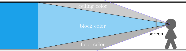
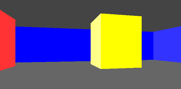
This gave us frames that consisted of solid floor and ceiling colors, and solid wall colors for boxes:
In this post we’ll add some textures. As before, this is all in C.

Wall Textures
We’ve already done most of the work required to render walls. Now, rather than drawing a column of pixels in a solid wall color, we’re instead going to render a column of pixels based on a wall texture.
After we’ve done the raycasting, we have our distance to the wall that we intersect and we have calculated the y-interval on the screen for the column of pixels we need to draw the wall in. In order to texture that wall, we need to find the corresponding column of pixels in the texture for that wall and render it into that column:
In Wolfenstein 3D, all textures are 64 x 64 pixels. This uniformity simplifies the problem.
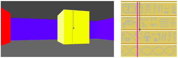
We have the collision location after intersecting with our world geometry. This collision location is decomposed into a block index (x and y) and the remainder \((x_\text{ref}, y_\text{ref})\) – the position within that tile:
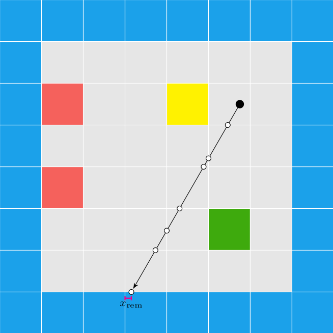
In this case, our tiles have width 1.0, to keep things simple. The world coordinate (3.152,1.000) is decomposed into tile indices (3,0) to give us the blue wall tile that we hit, and remainders (0.152, 1.000) to tell us where within the tile we hit. Because we always intersect at a point on the grid lines, one of our remainders is always either zero or one.
In this case, we use the \(x\) remainder to map into our texture. We’re viewing the texture from the north, so \(x_\text{rem} = 0.0\) corresponds to \(x_\text{texture} = 63\), and \(x_\text{rem} = 1.0\) corresponds to \(x_\text{texture} = 0.0\). The mapping in between is linear:
\[x_\text{texture} = 64 \frac{w_\text{tile} – x_\text{rem}}{w_\text{tile}}\]
The remainder we use, and whether we invert it, depends on the north/south/east/west direction the wall is facing. We can get this information from our decomposed coordinate:
f32 rem = 0.0f;
if (dx_ind == 0) {
   rem = dy_ind < 0 ? TILE_WIDTH - x_rem : x_rem;
} else {
   rem = dx_ind < 0 ? y_rem : TILE_WIDTH - y_rem;
}
u32 texture_x = min((int)(TEXTURE_SIZE*rem/TILE_WIDTH),TEXTURE_SIZE-1);
We have to cast \(x_\text{texture}\) to an integer to get our pixel index, and ‘and’ it by 64-1 to prevent accidental bounds issues.
Now that we have located our texture pixel column, we need to scan vertically through the screen’s pixel column and identify the corresponding pixel \(y\) positions in the texture as we go:
The pixel column on the screen is bounded between \(y_\text{hi}\) and \(y_\text{lo}\). The texture is a matrix, and so the \(y\) coordinate increases down the texture. Thus, our mapping is:
\[\begin{aligned} y = y_\text{hi} & \mapsto y_\text{texture} = 0 \\ y = y_\text{lo} & \mapsto y_\text{texture} = 63 \end{aligned}\]
with a linear mapping in between:
\[y_\text{texture} = 64 \frac{y_\text{hi} – y}{y_\text{hi} – y_\text{lo}} \]
(Note that we use 64 rather than 63 since we’ll be flooring this when we code it).
Our column-rendering code is thus:
u32 denom = max(1, y_hi - y_lo);
int y_lo_capped = max(y_lo, 0);
int y_hi_capped = min(y_hi, SCREEN_SIZE_Y-1);
for (int y = y_hi_capped; y >= y_lo_capped; y--) {
   u32 texture_y = (y_hi - y) * TEXTURE_SIZE / denom;
   u32 pixel_index = texture_y + texture_x*bitmap->n_pixels_per_column;
   u32 color = BITMAP_WALL.abgr[pixel_index];
   state.pixels[(y * SCREEN_SIZE_X) + x] = color;
}
We can make a slight optimization by factoring out the column lookup, and just increasing our pixel baseline:
u32 baseline = texture_y + texture_x*bitmap->n_pixels_per_column;
u32 denom = max(1, y_hi - y_lo);
int y_lo_capped = max(y_lo, 0);
int y_hi_capped = min(y_hi, SCREEN_SIZE_Y-1);
for (int y = y_hi_capped; y >= y_lo_capped; y--) {
   u32 texture_y = (y_hi - y) * TEXTURE_SIZE / denom;
   u32 color = BITMAP_WALL.abgr[texture_y+baseline];
   state.pixels[(y * SCREEN_SIZE_X) + x] = color;
}
We can calculate how many \(y\)-pixels to step every frame, and just use that instead:
u32 baseline = texture_y + texture_x*bitmap->n_pixels_per_column;
u32 denom = max(1, y_hi - y_lo);
f32 y_loc = (f32)((y_hi - y_hi_capped) * TEXTURE_SIZE) / denom;
f32 y_step = (f32)(TEXTURE_SIZE) / denom;
for (int y = y_hi_capped; y >= y_lo_capped; y--) {
   u32 texture_y = min((u32) (y_loc), TEXTURE_SIZE-1);
   u32 color = BITMAP_WALL.abgr[texture_y+baseline];
   state.pixels[(y * SCREEN_SIZE_X) + x] = color;
   y_loc += y_step;
}
This give us some nice texturing:
We can introduce a shading effect (also done in Wolfenstein 3D), by having different textures for north/south faces than east/west faces. I just have darkened copies of every texture. This makes the walls pop more, and subtly adds to the feeling of 3d immersion:
Speaking of multiple textures, let’s go ahead and do that:
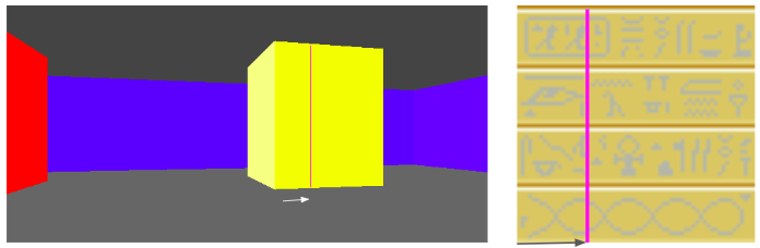
How do we achieve this? Well, first, rather than having a single 64 x 64 pixel texture, here I am using a sheet of textures:
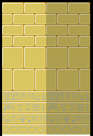
Right now this sheet has 2 columns, one for the lighter faces and one for the darker faces. It also currently has 3 wall types. To use a particular texture, we thus need to know its y index and whether it is light or dark. The wall type is based on the block type, which we store in our map data. We then apply a multiple of TEXTURE_WIDTH in the x and y directions when accessing this larger image:
u32 texture_x_offset = dx_ind == 0 ? 0 : TEXTURE_SIZE;
u32 texture_y_offset = (GetMapDataAt(x_ind,y_ind) - 1) * TEXTURE_SIZE;
Aside – Precompiled Texture Scans
I bought Fabien Sanglard’s Little Black Book on Wolfenstein 3D since writing the last post. It is a great overview of the original game, both technically and holistically. Now, the code written there looks and feels very different than the code we’re writing here, mainly because of the large differences in the hardware. Large parts of the book are about explaining how Wolfenstein 3D handled interrupts, was able to pipe pixel data through the VGA interface, and how fixed point arithmetic is used throughout the game’s logic.
I had a vague idea going into this project that the primary achievement behind Wolfenstein 3D was its raycasting engine. Yes, the raycasting engine was a breakthrough, but it is quite a small aspect in between myriad other engineering tricks that had to be pulled to get the game to run at a playable framerate back in the day.
One of the book’s tricks had to do with the texture column drawing code we just covered. Namely, this loop here:
for (int y = y_hi_capped; y >= y_lo_capped; y--) {
   u32 texture_y = min((u32) (y_loc), TEXTURE_SIZE-1);
   u32 color = BITMAP_WALL.abgr[texture_y+baseline]
   state.pixels[(y * SCREEN_SIZE_X) + x] = color;
   y_loc += y_step;
}
John Carmack (I’m assuming) had figured out a more efficient way to draw these pixel columns. In short, the machine code for these loops were precompiled for specific cases, and the renderer would just call the appropriate case. This would avoid all of the bookkeeping and for-loop if statements.
I learned that Wolfenstein 3D had hard-coded the player height to 1/2 the wall height, so y_lo_capped = y_hi_capped and y_lo = y_hi, always. This somewhat simplifies things. They could then precompile a loop based on the number of pixels in the column (which is 2*y_lo_capped). For example, if the column has height 2 (for a very distant wall), the precompiled function would be:
void draw_wall_2pix(
  uint32* screen_pixels,
  uint32* texture_pixels,
  uint32 screen_baseline,
  uint32 texture_baseline,
  ) {
  screen_pixels[screen_baseline++] = texture_pixels[texture_baseline];
  screen_pixels[screen_baseline++] = texture_pixels[texture_baseline+63];
}
Or, for 4 pixels:
void draw_wall_4pix(
  uint32* screen_pixels,
  uint32* texture_pixels,
  uint32 screen_baseline,
  uint32 texture_baseline,
  ) {
  screen_pixels[screen_baseline++] = texture_pixels[texture_baseline];
  screen_pixels[screen_baseline++] = texture_pixels[texture_baseline+16];
  screen_pixels[screen_baseline++] = texture_pixels[texture_baseline+32];
  screen_pixels[screen_baseline++] = texture_pixels[texture_baseline+63];
}
I thought that was a pretty neat trick. Sure, these precompiled functions take up space. (If I recall correctly, they generated one of these for every pixel column that was a multiple of 2, and used the closest). Drawing pixels is what the game is spending most of its time doing, so it makes sense to optimize. At least, it did back then. Right now I have no trouble hitting 60 Hz, so I don’t (yet) have to do this. (I’m also don’t have a full game – just some basic texture rendering).
Floor and Ceiling Textures
Wolfenstein 3D did not have floor and ceiling textures. Instead, it just filled them in with solid colors. In fact, it actually just filled in the floor and ceiling first and then drew the walls over that afterwards.
Ceiling and wall textures are similar to walls, we just have to work out the math again:
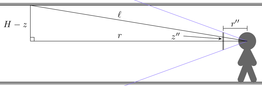
Here we have a ray cast through a pixel above the center of the screen such that it eventually hits the ceiling. The horizontal distance that the ray travels is \(r\), but the actual ray length is \(\ell\). From triangle similarity we get the same relation we used when working on walls in the previous post:
\[\frac{z”}{r”} = \frac{H-z}{r} \qquad \mapsto \qquad r = \frac{H-z}{z”} r”\]
We can calculate \(z”\) for a given pixel by calculating it from the pixel’s \(y\) index:
\[z” = \frac{y\, – \frac{1}{2}n_y}{n_y} h_\text{camera} \]
where \(n_y\) is the number of pixels in our screen’s y dimension, and \(h_\text{camera}\) is the camera’s physical height in world dimensions (a parameter we choose and can vary).
We’ve been using \(r” = 1\) for horizontal raycasting. Unfortunately, that’s only right when we cast a ray directly in the direction the player is facing. We have to adjust this by a small factor based on how far our pixel’s \(x\)-location is off from the screen’s center:
\[r” = \sqrt{1 + x_\delta^2}, \qquad x_\delta = \frac{x – \frac{1}{2}n_x}{n_x} w_\text{camera}\]
where \(n_x\) is the number of pixels in our screen’s x dimension and \(w_\text{camera}\) is the camera’s physical width in world dimensions (It should be related to \(n_y\) by our screen’s aspect ratio).
Knowing these, we can calculate the horizontal radius using the first equation:
int x, y; // pixel x and y coordinates, y > SCREEN_SIZE_Y/2
f32 x_delta = (x-SCREEN_SIZE_X/2.0f)/SCREEN_SIZE_X*state.camera_width;
f32 rpp = sqrt(1.0f + x_delta*x_delta);
f32 zpp = (y-(SCREEN_SIZE_Y/2.0f))*(state.camera_height/SCREEN_SIZE_Y);
f32 r = (WALL_HEIGHT - state.camera_z)*rpp/zpp;
The horizontal location where we intersect with the ceiling is simply \(r\) in the direction through the screen’s pixel relative to the camera’s direction. If the direction the camera is facing is \(\boldsymbol{\hat{b}}\), and \(\texttt{rotr}(\boldsymbol{\hat{b}})\) is the right-hand 90-degree rotated camera direction, then the horizontal raycast direction \(\boldsymbol{\hat{d}}\) is:
\[\begin{aligned} \boldsymbol{\hat{d}} &= \texttt{normalize}( \boldsymbol{\hat{b}} + x_\delta \texttt{rotr}(\boldsymbol{\hat{b}}) ) \\ &= \frac{1}{\sqrt{1 + x_\delta^2}} \left(\boldsymbol{\hat{b}} + x_\delta \texttt{rotr}(\boldsymbol{\hat{b}}\right) \\ &= \frac{1}{r”} \left(\boldsymbol{\hat{b}} + x_\delta \texttt{rotr}(\boldsymbol{\hat{b}}\right) \end{aligned}\]
This makes the horizontal 2D intersection point:
\[\begin{aligned} \boldsymbol{p}_\text{hit} &= \boldsymbol{p}_\text{camera} + r \boldsymbol{\hat{d}} \\ &= \boldsymbol{p}_\text{camera} + r \frac{1}{r”} \left(\boldsymbol{\hat{b}} + x_\delta \texttt{rotr}(\boldsymbol{\hat{b}})\right) \\ & = \boldsymbol{p}_\text{camera} + \left((H – z_\text{camera}) \frac{r”}{z”}\right) \frac{1}{r”} \left(\boldsymbol{\hat{b}} + x_\delta \texttt{rotr}(\boldsymbol{\hat{b}})\right) \\ &= \boldsymbol{p}_\text{camera} + \frac{H – z_\text{camera}}{z”} \left(\boldsymbol{\hat{b}} + x_\delta \texttt{rotr}(\boldsymbol{\hat{b}})\right) \end{aligned}\]
It turns out, we don’t need to calculate \(r”\) at all!
Once we have the location of the intersection, we can use fmod based on the tile width to get the position in that texture relative to its local coordinates. We then use that texture location to set the pixel color:
u32 texture_x = (int)(fmod(hit_x,TILE_WIDTH)/TILE_WIDTH*TEXTURE_SIZE)
                      & (TEXTURE_SIZE-1);
u32 texture_y = (int)(fmod(hit_y,TILE_WIDTH)/TILE_WIDTH*TEXTURE_SIZE)
                      & (TEXTURE_SIZE-1);
u32 color = GetColumnMajorPixelAt(&BITMAP_FLOOR,
               texture_x+texture_x_offset, texture_y+texture_y_offset);
state.pixels[(y * SCREEN_SIZE_X) + x] = color;
While this is technically enough to get ceiling pixels on the screen, the current method requires a raycast for every pixel. We can greatly simplify this.
We can use the fact that all of the intersection points for a given row of pixels lie on a line:
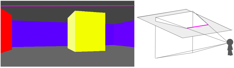
This means that, for every pixel row, we only need to compute the intersection points for the leftmost and rightmost pixel, and then we can interpolate between them.
// Ray direction for x = 0
f32 half_camera_width = state.camera_width/2.0f;
f32 ray_dir_lo_x = state.camera_dir.x +
        half_camera_width*state.camera_dir_rotr.x;
f32 ray_dir_lo_y = state.camera_dir.y +
        half_camera_width*state.camera_dir_rotr.y;

// Ray direction for x = SCREEN_SIZE_X
f32 ray_dir_hi_x = state.camera_dir.x -
        half_camera_width*state.camera_dir_rotr.x;
f32 ray_dir_hi_y = state.camera_dir.y -
        half_camera_width*state.camera_dir_rotr.y;

// Draw ceiling
for (int y = SCREEN_SIZE_Y/2 + 1; y < SCREEN_SIZE_Y; y++) {
   // Radius
   f32 zpp = (y-(SCREEN_SIZE_Y/2.0f))*(state.camera_height/SCREEN_SIZE_Y);
   f32 radius = (WALL_HEIGHT-state.camera_z)/zpp;

   // Location of the 1st ray's intersection
   f32 hit_x = state.camera_pos.x + radius * ray_dir_lo_x;
   f32 hit_y = state.camera_pos.y + radius * ray_dir_lo_y;

   // Each step toward hit2
   f32 step_x = radius*(ray_dir_hi_x-ray_dir_lo_x)/SCREEN_SIZE_X;
   f32 step_y = radius*(ray_dir_hi_y-ray_dir_lo_y)/SCREEN_SIZE_X;

   for (int x = 0; x < SCREEN_SIZE_X; x++) {
      int x_ind_hit = (int)(floorf(hit_x/TILE_WIDTH));
      int y_ind_hit = (int)(floorf(hit_y/TILE_WIDTH));
      f32 x_rem_hit = hit_x - TILE_WIDTH*x_ind_hit;
      f32 y_rem_hit = hit_y - TILE_WIDTH*y_ind_hit;

      u32 texture_x = (int)(x_rem_hit/TILE_WIDTH * TEXTURE_SIZE);
      u32 texture_y = (int)(y_rem_hit/TILE_WIDTH * TEXTURE_SIZE);
      u32 color = GetColumnMajorPixelAt(&BITMAP,texture_x,texture_y);
      state.pixels[(y * SCREEN_SIZE_X) + x] = color;
      // step
      hit_x += step_x;
      hit_y += step_y;
      }
}
We can render the floor in the same way.
Combining the two, and then rendering our walls on top of it, gives us:
Right now we’re just rendering a single repeated texture for both the floor and the ceiling. We can, if we want, specify floor and ceiling textures on a per-cell basis in much the same way that we specify wall types. This just involves figuring out the tile index of the intersection (handling cases where we see pixels outside of the map’s bounds) and then rendering from the corresponding texture.
Conclusion
This post took our colored blocky Wolfenstein level and textured it. We started with wall textures, which we can draw at the appropriate height given our raycast distance. We have to figure out which column to render from our texture, and then scale it appropriately as we render it. For this reason, the wall textures are stored in column-major order.
We then added floor and ceiling textures, which we render first to avoid having to figure out occlusion with the walls. That makes raycasting trivial. However, unlike walls, the floors and ceiling are at a weird angle with respect to our camera heading. The big simplification here comes from being able to linearly interpolate across the screen.
Once again we were able to leverage what basically amounts to trigonometry and some indexing in order to get some neat interactive results.
This post did not cover texture creation and loading. In short, I created them in Gimp, saved them to .tif, and wrote a simple Julia script to export them into an assets binary. The code can thus load a single assets file and just point into that. I might talk about this in a future post.
The code for this demo is available here (with assets here).