Taking TOOM Off-Grid, without BSPs

I’ve continued tinkering with my little C software renderer covered in previous blog posts. So far we’ve rendered a blocky, textured environment reminiscent of Wolfenstein 3D:

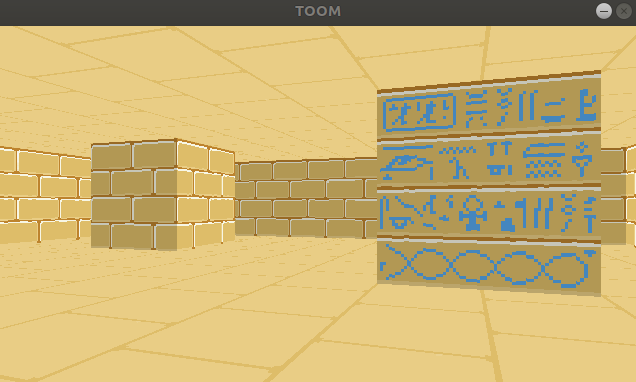
You’ll notice from the window header that the project is called TOOM, as in, Tim DOOM. It isn’t Timenstein 3D, so we have some work to do.

In this blog post we’ll go off-grid and move to general 2D geometry.

Binary Space Partitioning

John Carmack’s great innovation in creating DOOM, the design change that made rendering general 2D geometry in a constrained computing environment possible, was the BSP tree. BSP trees make it efficient to walk over the surfaces in your world in a front-to-back order, based on the camera location.

Each node in the tree represents a splitting plane (or line, rather, as this is 2D) that subdivides the level. All faces below that node lie entirely on one or the other side of that dividing line. At the bottom of the tree you get leaf nodes, which each represent a single convex map region:

DOOM’s E1M1 map, image from the doomwiki

While the BSP tree is a genius addition, it does come with its disadvantages. The main one being its construction. For DOOM this meant running Node Builder after level design, a process that does a lot of iteration to find the best splitting planes for a well-balanced tree. Not only does this take a while, it also requires the level geometry to remain static. This means no 2D geometry changes. (DOOM’s doors all move vertically).

I kind of want to be able to support geometry changes. Plus, I kind of like the idea of figuring out something different. So, we’re going to take another approach.

Keep on Raycasting

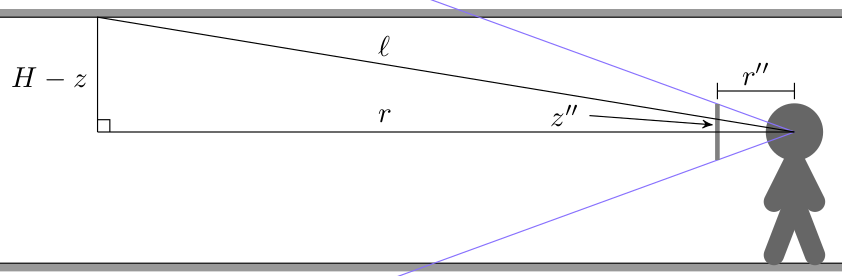
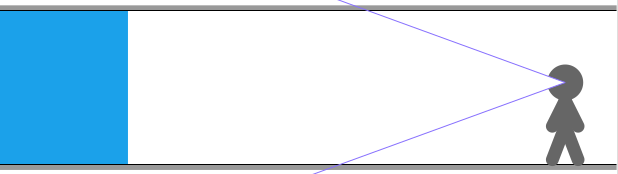
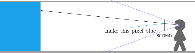
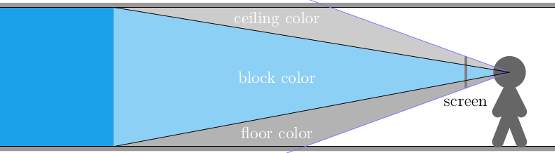
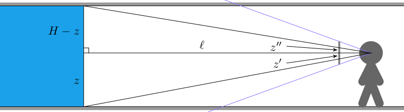
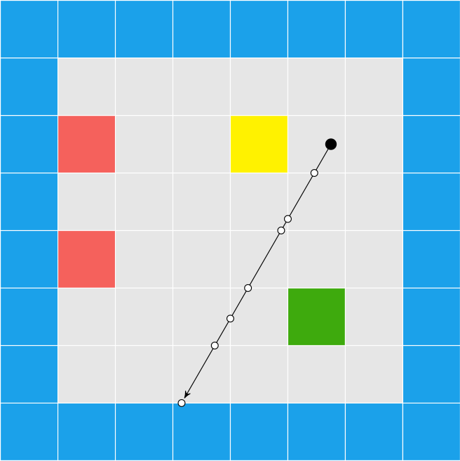
In Wolfenstein Raycasting in C, we talked about how the software renderer casts rays out into the world for every pixel column in the screen:

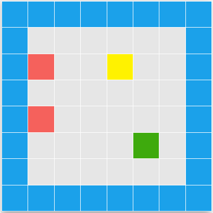
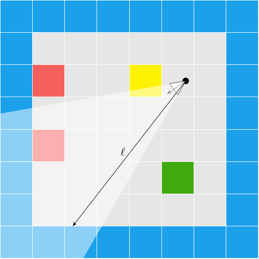
This raycasting was fairly efficient because we limited our geometry to a regular grid:

Now, we’re going to do the exact same thing, except on a triangle mesh:

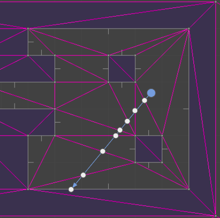
Moving to a triangle mesh has several consequences. On the plus side, it supports general 2D geometry, so we no longer have to constrain ourselves to a grid of blocks. We can fairly easily move vertices and mutate our environment. On the other hand, casting a ray through a set of triangles tends to be more computationally expensive, we have to develop and maintain a more complicated data structure, and we aren’t entirely free to mutate our environment – our triangles have to remain valid (right-handed).

It isn’t 1993 anymore, so I’m hoping that the performance hit from raycasting on a mesh isn’t too bad on a modern processor. I’ve already been tinkering with triangle meshes, so I’m eager to adapt what I learned there to this new application. I also think we can overcome the editing limitations.

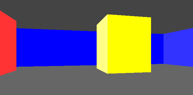
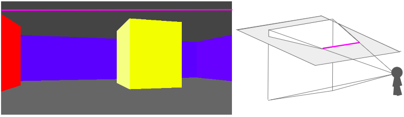
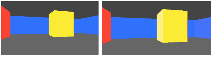
Below is a GIF from TOOM. The left half of the image is rendered with the new triangle meshes. The right half of the image is rendered with the old blocky technique. (The new map was made to be identical to the old one, for now). The textures assigned to the walls aren’t the same just yet, so you can see a fairly clear division.

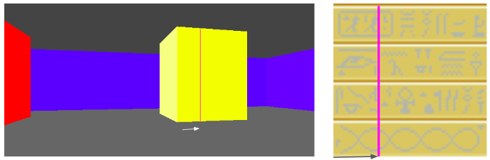
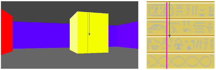
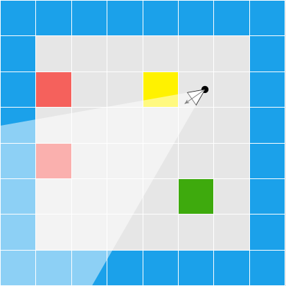
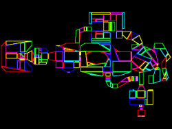
The debug view gives us a better sense of what is going on:

Raycasting through triangles is the same, conceptually, as raycasting through a grid. We keep casting through cells until we reach a solid cell. Now, instead of square cells with regular spacing, we have arbitrarily-sized, triangular cells.

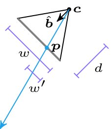
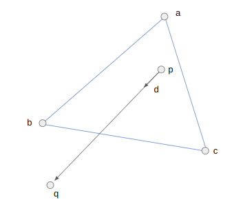
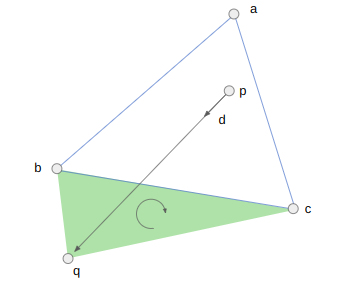
Each raycast starts with a ray at the camera location \(\boldsymbol{p}\) heading in a direction \(\hat{\boldsymbol{d}}\). As we iterate \(\boldsymbol{p}\) will be shifted out into the world. In the first iteration, \(\boldsymbol{p}\) will be the camera location and can lie inside a triangle face. In future iterations, \(\boldsymbol{p}\) is lies on an edge that we crossed in the previous iteration.

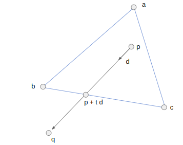
We take the three bounding vertices \(\boldsymbol{a}\), \(\boldsymbol{b}\), and \(\boldsymbol{c}\) and intersect the line through \(\boldsymbol{p}\) with the direction \(\hat{\boldsymbol{d}}\) with AB, BC, and CA, representing each intersection point as \(\boldsymbol{p}’ = \boldsymbol{p} + t \hat{\boldsymbol{d}}\). We step forward to the edge that we hit first. That is, the edge for which \(t\) is smallest (but positive). We ignore any edge we are already on.

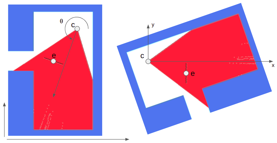
We start by computing \(\boldsymbol{q}\), a point far enough along \(\boldsymbol{d}\) that it should exit the triangle:

Before we calculate an intercept, we can disregard checking an edge EF if the triangle EFQ is not left-handed. This helps us avoid cases where an intersection will either never occur or lie behind our ray. For example, we can skip checking AB because ABQ is right-handed (counter-clockwise):

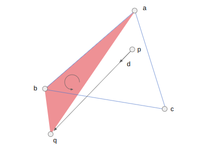
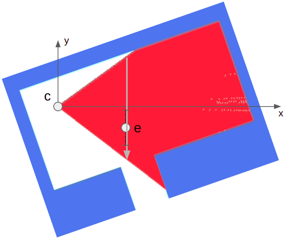
We should check BC, because the triangle BCQ is left-handed (clockwise):

We can now calculate the interection point’s \(t\)-value. For the edge BC, this is:

\[t_{BC} = \frac{(\boldsymbol{c}-\boldsymbol{b}) \times (\boldsymbol{p}-\boldsymbol{b})}{(\boldsymbol{q}-\boldsymbol{p}) \times (\boldsymbol{c}-\boldsymbol{b})}\]

In code, this works out to:

if (GetRightHandedness(b, c, q) < -eps) {
   // We would cross BC
   v2 v = c - b;
   v2 w = p - b;
   f32 t_bc = cross(v, w) / cross(q - p, v);
   if (t_bc < t_min) {
      t_min = t_bc;
      qe_side = qe_bc;
      v_face = v;
   }
}

We just repeat this block three times, once for each edge. Each time we get an intersection, we keep it if it is earlier than any previous intersection. When we do, we also store the edge that we pass over (via its quarter edge in the DCEL).

Just like before, we propagate our point \(\boldsymbol{p}\) up to the new edge and then either iterate again if the new face is empty, or break out if the new face is solid.

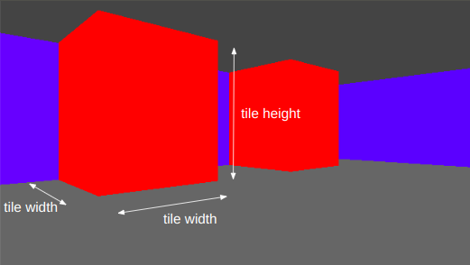
We do have to make some minor modifications in how we access the face texture. With the grid we could safely assume that every wall was square, with a corresponding 64×64 pixel texture. Now walls can have arbitrary aspect ratios, so we have to do a tiny bit of math to index into the texture based on our intersection location along the edge:

f32 PIX_PER_DISTANCE = TEXTURE_SIZE / TILE_WIDTH;
QuarterEdge *qe_face_src = qe_dual->rot->rot->rot;
f32 x_along_texture = length(v_face) - length(pos - qe_face_src->vertex);
u32 texture_x = (int)(PIX_PER_DISTANCE * x_along_texture) % TEXTURE_SIZE;

Collision Detection

One immediate advantage of using the DCEL is that we can leverage it for collision detection. In DOOM, collision detection is done via a blockmap, which is just a discrete 128×128 pixel grid. Each grid cell stores the lines in that block. An entity moving in a cell can just check for collision against all of the lines in the cell. The blockmap is constructed on level export, and again assumes static 2D geometry.

We don’t have to use a bockmap, because we have the DCEL. We can simply store the face that our player is in and check for collisions every time we move them. Our player movement code is the same as the player movement code in this previous blog post. Any time we would cross over a solid edge between two faces, we simply move up to the edge instead, and lose any velocity into the edge.

The current approach assumes the player is a single point. If we want, we can create a second collision mesh that uses inflated solid geometry to compensate for the player’s collision volume. We would have to keep that second mesh synchronized with any changes to the geometry mesh.

DCELs make pathing and shooting computations easy too. DCELs are primarily used in games for pathing (via Nav Meshes) and collision checking for a gunshot is just a raycast where we also care about intersections with enemies.

Game Map Representation

The biggest difference here was not so much the rendering code, but more the integration of the mesh data structure and how we represent the game map. With the Wolfenstein-style renderer we were able to represent the map using 2D arrays:

tiles = UInt8[
    1 1 1 1 1 1 1 1 2 1 1 1 2;
    1 0 0 0 0 0 0 1 2 0 0 0 2;
    1 0 0 3 0 0 2 2 2 0 0 0 2;
    1 0 0 0 0 0 0 0 0 0 0 0 2;
    1 0 0 0 0 0 2 2 2 0 0 0 2;
    1 0 2 0 0 0 0 1 2 0 0 0 2;
    1 0 0 0 0 0 0 1 2 0 0 0 2;
    1 1 1 1 1 1 1 1 2 3 3 3 2]

floor = UInt8[
    1 1 1 1 1 1 1 1 2 1 1 1 2;
    1 4 4 4 4 4 4 1 2 5 5 5 2;
    1 4 4 3 4 4 2 2 2 5 5 5 2;
    1 4 4 4 4 4 2 2 2 5 5 5 2;
    1 4 4 4 4 4 2 2 2 5 5 5 2;
    1 4 2 4 4 4 4 1 2 5 5 5 2;
    1 4 4 4 4 4 4 1 2 5 5 5 2;
    1 1 1 1 1 1 1 1 2 3 3 3 2]

ceiling = UInt8[
    1 1 1 1 1 1 1 1 2 1 1 1 2;
    1 4 4 4 4 4 4 1 2 4 4 4 2;
    1 4 4 3 4 4 2 2 2 4 4 4 2;
    1 4 4 4 4 4 2 2 2 4 4 4 2;
    1 4 4 4 4 4 2 2 2 4 4 4 2;
    1 4 2 4 4 4 4 1 2 4 4 4 2;
    1 4 4 4 4 4 4 1 2 4 4 4 2;
    1 1 1 1 1 1 1 1 2 3 3 3 2]

Each cell could thus be marked as solid or not depending on whether the cell’s entry in tiles is 0. Nonzero values corresponded to texture indices. Similar arrays were used for the floor and ceiling textures.

With the general 2D geometry, we no longer have a convenient text short-hand. The DCEL has a lot of pointers and is no fun to edit manually. We have to store all vertices, quarter edges, and the associations between them. We then optionally mark edges as being solid, and when we do, set edge texture information.

At this point the game map consists of two things:

  • a triangle mesh
  • optional side information

My representation for side information is pretty simple. It is just a structure with some flags, a texture id, texture x and y offsets, and the associated quarter edge:

// The information associated with one side of an edge between vertices in 
// the map. If this represents the directed edge A->B, then it describes the
// edge viewed on the right side of A->B.
struct SideInfo {
    u16 flags;
    u16 texture_id;
    i16 x_offset;
    i16 y_offset;
    QuarterEdgeIndex qe;
};

The map data is packed into the binary assets blob (similar to a DOOM WAD file) and loaded by the game at start.

Editing this game data is rather hard to do by hand, so I started working on an editor on the side. The editor is written in C++, and I allow myself the use of whatever libraries I want. I might go over that in more detail in a future post, but for now I just want to show how it can be used to adjust the map:

The gif here is fairly large. It may have to be viewed separately.

Having an editors gives us a place to put supporting code and lets us use more convenient data structures that aren’t streamlined for the C software renderer. The editor can then do the lifting required to export our game data into the form expected by the game.

Conclusion

The TOOM source code for this post is available here. I have been overwriting my assets file, and the new ones are no longer compatible, so unfortunately do not have a good assets file to share.

In this post we took our blocky Wolfenstein-style environment and moved to general 2D geometry. We didn’t follow DOOM and use a BSP, but instead stuck with raycasting and used a DCEL.

What we have now is much closer to DOOM, but still lacks a few things. Geometrically, we don’t have variable floor heights, which means we also don’t yet worry about wall surfaces between variable floor heights. We also aren’t animating doors or elevators, and we don’t have textures with transparency. We aren’t doing any lighting, other than manually setting some faces to be darker. DOOM really was groundbreaking.

Billboard Sprites

I’m still on a Wolfenstein 3D kick, so this month we’re going to further extend the software render. We’re doing it in C and are manually setting individual pixels (no 3D lib). As before, I’m deriving this myself, so while we should end up with something similar to Wolfenstein 3D, things are probably not going to be a perfect match.

The last post left us with a textured blocky world. I felt like the next thing to do was to be able to populate that world.

Wolfenstein 3D (and DOOM) were before the time of 3d meshes. Enemies and set pieces (like barrels) were rendered as flat images. These billboard sprites always face the camera, since that simplifies the rendering math:

In Wolfenstein 3d, all wall textures are 64×64 images. They kept things simple and made all sprites 64×64 images as well. Unlike wall textures which were always solid, sprites have a bunch of fully transparent pixels. This was indicated using magenta.

Behold my fantastic programmer art:

We can load this image in like we do with our wall textures. Now we just have to figure out how to render it.

Render Math

Each entity has a position in 3D space. First we transform the object’s location in game space to a camera-relative space:

We can do this with:

\[ \begin{bmatrix} e’_x \\ e’_y \end{bmatrix} = \begin{bmatrix} \hphantom{-}\cos \theta & \sin \theta \\ -\sin \theta & \cos \theta \end{bmatrix} \begin{bmatrix} e_x – c_x \\ e_y – c_y \end{bmatrix} \]

We can skip rendering the entity at this point if it is behind the camera (\(e’_x < 0\)).

Next we calculate its extents in the screen’s horizontal dimension:

The billboard’s width is the same as the tile width. We can do some math to get the camera x-pixel locations:

\[\begin{aligned} x_\text{lo} = \left(\frac{1}{2} – \frac{e’_y + w_\text{sprite}/2}{e’_x \, \text{fov}_x}\right) \text{screenpix}_x \\ x_\text{hi} = \left(\frac{1}{2} – \frac{e’_y – w_\text{sprite}/2}{e’_x \, \text{fov}_x}\right) \text{screenpix}_x \end{aligned}\]

We’re just moving half the sprite width in either direction, then dividing by the screen’s width at the entity’s location. We have to flip about 0.5 because pixels go left to right in screen space, and then scale up by the number of pixels.

The image’s height is determined by the distance the entity is from the camera. The calculation is the same one we used for determining the height of walls. This gives us \(y_\text{lo}\) and \(y_\text{hi}\).

Now we can iterate from \(x_\text{lo}\) to \(x_\text{hi}\) in 1-pixel increments, rendering each column of pixels as we go between \(y_\text{lo}\) and \(y_\text{hi}\). For every \(x\)-increment of 1 pixel we move \(64 / (x_\text{hi} – x_\text{lo})\) pixels horizontally in the sprite image. Similarly, for every \(y\)-increment of 1 pixel we move \(64 / (y_\text{hi} – y_\text{lo})\) pixels vertically in the sprite image.

This gives us a billboard sprite in the correct location that scales as we move closer or farther away. Unfortunately, we’re rendering the magenta pixels and we’re drawing over walls that should be blocking our view.

We can trivially skip rendering magenta pixels with an if statement.

Fixing the wall occlusions also turns out to be pretty simple. We are rendering the entity after we render the walls. When we render the walls we have to calculate the raycast distance. We keep track of this distance for each pixel column, and only render a given entity pixel column when it is closer to the camera.

So there we have it – billboard sprites with occlusions. We first render the floors and ceilings, we then render the walls, and we then finally render all entity sprites.

DOOM Sprites

Unfortunately, my programmer art is pretty terrible. It works okay for the walls, ceilings, and floors, but it doesn’t work so well for entities.

I considered using Wolfenstein 3D sprites, but I don’t want to go with the Nazi theme. I decided to go with DOOM sprites since the assets are easily available (and have been used by modders for decades).

We have to do some work to load from the DOOM assets (stored in a WAD file). I was surprised to find that the WAD format is quite similar to the asset format I made up that I was already using. They both consist of a header, followed by a series of blobs, terminated with a table of contents. We can just load the whole thing into memory and then point to the data we need.

Wolfenstein 3D stored everything in 64×64 images. DOOM was a bigger project, with things of different sizes, and so went for a more compressed format (at the expense of added complexity). Sprites are stored as patches, which slice the image up by pixel column, and only specify continuous pixel column regions that should be drawn (ignoring transparent pixels).

We don’t have to waste any space on transparent columns:

Many columns simply consist of a single continuous range of pixels:

Some columns have several pixel intervals:

Each patch has a header defining its width and height, and its position relative to the entity’s origin. (If a monster has an arm stretched out to the left, we want to know to offset the image to the left a bit). This is followed by byte offsets to pixel data. One of the cool things here is that if two pixel columns happen to be the same, we don’t have to store them twice, but can just point to the same data.

Pixel columns are each a sequence of pixel intervals with a given offset from vertical, some number of pixels, and then the pixel values. We know we’ve reached the end when the vertical offset is 0xFF.

DOOM is restricted to a 256-color palette. The pixel data in each patch stores 1-byte indices into this palette. When rendering, we take the index and look up the appropriate color. (DOOM also has a colormap that it uses to darken things further from the camera, but I’m not doing that quite yet).

While DOOM does use billboard sprites, they also rendered each frame from 8 different viewing angles. We can determine which sprite to use for a given frame based on our viewing angle:

f32 monster_heading_rel = 
                 fmod(monster_heading+camera_heading+PI+PI/8.0,2*PI);
int monster_frame = (int)(monster_heading_rel * 8.0/(2.0*PI)) & 0x07;

This gives us some nice visual continuity as we walk around the monster:

Conclusion

The code for this post is available here. The zip file contains my assets, but you’ll have to separately find the DOOM assets, since I didn’t think it’s okay to host them myself. Thank you DOOM team for making those available!

I ended up splitting my source code into multiple files, since the code was steadily growing and becoming less manageable. You’ll notice that I use fewer static functions and I pass in the objects that I use instead.

The code now generates a second window, in which I render a top-down debug view. I allow myself to use SDL_RenderDrawLine and SDL_RenderFillRect here. (They’d be pretty easy to implement myself, but whatever).

I’m not sure how far I’ll take this project. It certainly has been fun so far! Fully fleshed games are pretty involved, and as we’ve seen I am pretty limited when it comes to asset creation. I do have a neat idea that I want to try out with respect to more general 3D rendering and collision detection, and I kind of want to have some rudimentary monster fighting interactions. We’ll see.

Textures for Wolfenstein

In the previous post we derived raycasting for a game in the style of Wolfenstein 3D. That is, a blocky game world with a regular grid and with the player’s view restricted to looking out horizontally. These restrictions let us simplify rendering significantly. At the end of the last post we were drawing colored blocks by casting a ray out into the world for every pixel column, and drawing the appropriate color after some geometry based on the distance the ray traveled before hitting the wall:

This gave us frames that consisted of solid floor and ceiling colors, and solid wall colors for boxes:

In this post we’ll add some textures. As before, this is all in C.

Wall Textures

We’ve already done most of the work required to render walls. Now, rather than drawing a column of pixels in a solid wall color, we’re instead going to render a column of pixels based on a wall texture.

After we’ve done the raycasting, we have our distance to the wall that we intersect and we have calculated the y-interval on the screen for the column of pixels we need to draw the wall in. In order to texture that wall, we need to find the corresponding column of pixels in the texture for that wall and render it into that column:

In Wolfenstein 3D, all textures are 64 x 64 pixels. This uniformity simplifies the problem.

We have the collision location after intersecting with our world geometry. This collision location is decomposed into a block index (x and y) and the remainder \((x_\text{ref}, y_\text{ref})\) – the position within that tile:

In this case, our tiles have width 1.0, to keep things simple. The world coordinate (3.152,1.000) is decomposed into tile indices (3,0) to give us the blue wall tile that we hit, and remainders (0.152, 1.000) to tell us where within the tile we hit. Because we always intersect at a point on the grid lines, one of our remainders is always either zero or one.

In this case, we use the \(x\) remainder to map into our texture. We’re viewing the texture from the north, so \(x_\text{rem} = 0.0\) corresponds to \(x_\text{texture} = 63\), and \(x_\text{rem} = 1.0\) corresponds to \(x_\text{texture} = 0.0\). The mapping in between is linear:

\[x_\text{texture} = 64 \frac{w_\text{tile} – x_\text{rem}}{w_\text{tile}}\]

The remainder we use, and whether we invert it, depends on the north/south/east/west direction the wall is facing. We can get this information from our decomposed coordinate:

f32 rem = 0.0f;
if (dx_ind == 0) {
   rem = dy_ind < 0 ? TILE_WIDTH - x_rem : x_rem;
} else {
   rem = dx_ind < 0 ? y_rem : TILE_WIDTH - y_rem;
}
u32 texture_x = min((int)(TEXTURE_SIZE*rem/TILE_WIDTH),TEXTURE_SIZE-1);

We have to cast \(x_\text{texture}\) to an integer to get our pixel index, and ‘and’ it by 64-1 to prevent accidental bounds issues.

Now that we have located our texture pixel column, we need to scan vertically through the screen’s pixel column and identify the corresponding pixel \(y\) positions in the texture as we go:

The pixel column on the screen is bounded between \(y_\text{hi}\) and \(y_\text{lo}\). The texture is a matrix, and so the \(y\) coordinate increases down the texture. Thus, our mapping is:

\[\begin{aligned} y = y_\text{hi} & \mapsto y_\text{texture} = 0 \\ y = y_\text{lo} & \mapsto y_\text{texture} = 63 \end{aligned}\]

with a linear mapping in between:

\[y_\text{texture} = 64 \frac{y_\text{hi} – y}{y_\text{hi} – y_\text{lo}} \]

(Note that we use 64 rather than 63 since we’ll be flooring this when we code it).

Our column-rendering code is thus:

u32 denom = max(1, y_hi - y_lo);
int y_lo_capped = max(y_lo, 0);
int y_hi_capped = min(y_hi, SCREEN_SIZE_Y-1);
for (int y = y_hi_capped; y >= y_lo_capped; y--) {
   u32 texture_y = (y_hi - y) * TEXTURE_SIZE / denom;
   u32 pixel_index = texture_y + texture_x*bitmap->n_pixels_per_column;
   u32 color = BITMAP_WALL.abgr[pixel_index];
   state.pixels[(y * SCREEN_SIZE_X) + x] = color;
}

We can make a slight optimization by factoring out the column lookup, and just increasing our pixel baseline:

u32 baseline = texture_y + texture_x*bitmap->n_pixels_per_column;
u32 denom = max(1, y_hi - y_lo);
int y_lo_capped = max(y_lo, 0);
int y_hi_capped = min(y_hi, SCREEN_SIZE_Y-1);
for (int y = y_hi_capped; y >= y_lo_capped; y--) {
   u32 texture_y = (y_hi - y) * TEXTURE_SIZE / denom;
   u32 color = BITMAP_WALL.abgr[texture_y+baseline];
   state.pixels[(y * SCREEN_SIZE_X) + x] = color;
}

We can calculate how many \(y\)-pixels to step every frame, and just use that instead:

u32 baseline = texture_y + texture_x*bitmap->n_pixels_per_column;
u32 denom = max(1, y_hi - y_lo);
f32 y_loc = (f32)((y_hi - y_hi_capped) * TEXTURE_SIZE) / denom;
f32 y_step = (f32)(TEXTURE_SIZE) / denom;
for (int y = y_hi_capped; y >= y_lo_capped; y--) {
   u32 texture_y = min((u32) (y_loc), TEXTURE_SIZE-1);
   u32 color = BITMAP_WALL.abgr[texture_y+baseline];
   state.pixels[(y * SCREEN_SIZE_X) + x] = color;
   y_loc += y_step;
}

This give us some nice texturing:

We can introduce a shading effect (also done in Wolfenstein 3D), by having different textures for north/south faces than east/west faces. I just have darkened copies of every texture. This makes the walls pop more, and subtly adds to the feeling of 3d immersion:

Speaking of multiple textures, let’s go ahead and do that:

How do we achieve this? Well, first, rather than having a single 64 x 64 pixel texture, here I am using a sheet of textures:

Right now this sheet has 2 columns, one for the lighter faces and one for the darker faces. It also currently has 3 wall types. To use a particular texture, we thus need to know its y index and whether it is light or dark. The wall type is based on the block type, which we store in our map data. We then apply a multiple of TEXTURE_WIDTH in the x and y directions when accessing this larger image:

u32 texture_x_offset = dx_ind == 0 ? 0 : TEXTURE_SIZE;
u32 texture_y_offset = (GetMapDataAt(x_ind,y_ind) - 1) * TEXTURE_SIZE;

Aside – Precompiled Texture Scans

I bought Fabien Sanglard’s Little Black Book on Wolfenstein 3D since writing the last post. It is a great overview of the original game, both technically and holistically. Now, the code written there looks and feels very different than the code we’re writing here, mainly because of the large differences in the hardware. Large parts of the book are about explaining how Wolfenstein 3D handled interrupts, was able to pipe pixel data through the VGA interface, and how fixed point arithmetic is used throughout the game’s logic.

I had a vague idea going into this project that the primary achievement behind Wolfenstein 3D was its raycasting engine. Yes, the raycasting engine was a breakthrough, but it is quite a small aspect in between myriad other engineering tricks that had to be pulled to get the game to run at a playable framerate back in the day.

One of the book’s tricks had to do with the texture column drawing code we just covered. Namely, this loop here:

for (int y = y_hi_capped; y >= y_lo_capped; y--) {
   u32 texture_y = min((u32) (y_loc), TEXTURE_SIZE-1);
   u32 color = BITMAP_WALL.abgr[texture_y+baseline]
   state.pixels[(y * SCREEN_SIZE_X) + x] = color;
   y_loc += y_step;
}

John Carmack (I’m assuming) had figured out a more efficient way to draw these pixel columns. In short, the machine code for these loops were precompiled for specific cases, and the renderer would just call the appropriate case. This would avoid all of the bookkeeping and for-loop if statements.

I learned that Wolfenstein 3D had hard-coded the player height to 1/2 the wall height, so y_lo_capped = y_hi_capped and y_lo = y_hi, always. This somewhat simplifies things. They could then precompile a loop based on the number of pixels in the column (which is 2*y_lo_capped). For example, if the column has height 2 (for a very distant wall), the precompiled function would be:

void draw_wall_2pix(
  uint32* screen_pixels,
  uint32* texture_pixels,
  uint32 screen_baseline,
  uint32 texture_baseline,
  ) {
  screen_pixels[screen_baseline++] = texture_pixels[texture_baseline];
  screen_pixels[screen_baseline++] = texture_pixels[texture_baseline+63];
}

Or, for 4 pixels:

void draw_wall_4pix(
  uint32* screen_pixels,
  uint32* texture_pixels,
  uint32 screen_baseline,
  uint32 texture_baseline,
  ) {
  screen_pixels[screen_baseline++] = texture_pixels[texture_baseline];
  screen_pixels[screen_baseline++] = texture_pixels[texture_baseline+16];
  screen_pixels[screen_baseline++] = texture_pixels[texture_baseline+32];
  screen_pixels[screen_baseline++] = texture_pixels[texture_baseline+63];
}

I thought that was a pretty neat trick. Sure, these precompiled functions take up space. (If I recall correctly, they generated one of these for every pixel column that was a multiple of 2, and used the closest). Drawing pixels is what the game is spending most of its time doing, so it makes sense to optimize. At least, it did back then. Right now I have no trouble hitting 60 Hz, so I don’t (yet) have to do this. (I’m also don’t have a full game – just some basic texture rendering).

Floor and Ceiling Textures

Wolfenstein 3D did not have floor and ceiling textures. Instead, it just filled them in with solid colors. In fact, it actually just filled in the floor and ceiling first and then drew the walls over that afterwards.

Ceiling and wall textures are similar to walls, we just have to work out the math again:

Here we have a ray cast through a pixel above the center of the screen such that it eventually hits the ceiling. The horizontal distance that the ray travels is \(r\), but the actual ray length is \(\ell\). From triangle similarity we get the same relation we used when working on walls in the previous post:

\[\frac{z”}{r”} = \frac{H-z}{r} \qquad \mapsto \qquad r = \frac{H-z}{z”} r”\]

We can calculate \(z”\) for a given pixel by calculating it from the pixel’s \(y\) index:

\[z” = \frac{y\, – \frac{1}{2}n_y}{n_y} h_\text{camera} \]

where \(n_y\) is the number of pixels in our screen’s y dimension, and \(h_\text{camera}\) is the camera’s physical height in world dimensions (a parameter we choose and can vary).

We’ve been using \(r” = 1\) for horizontal raycasting. Unfortunately, that’s only right when we cast a ray directly in the direction the player is facing. We have to adjust this by a small factor based on how far our pixel’s \(x\)-location is off from the screen’s center:

\[r” = \sqrt{1 + x_\delta^2}, \qquad x_\delta = \frac{x – \frac{1}{2}n_x}{n_x} w_\text{camera}\]

where \(n_x\) is the number of pixels in our screen’s x dimension and \(w_\text{camera}\) is the camera’s physical width in world dimensions (It should be related to \(n_y\) by our screen’s aspect ratio).

Knowing these, we can calculate the horizontal radius using the first equation:

int x, y; // pixel x and y coordinates, y > SCREEN_SIZE_Y/2
f32 x_delta = (x-SCREEN_SIZE_X/2.0f)/SCREEN_SIZE_X*state.camera_width; 
f32 rpp = sqrt(1.0f + x_delta*x_delta);
f32 zpp = (y-(SCREEN_SIZE_Y/2.0f))*(state.camera_height/SCREEN_SIZE_Y);
f32 r = (WALL_HEIGHT - state.camera_z)*rpp/zpp;

The horizontal location where we intersect with the ceiling is simply \(r\) in the direction through the screen’s pixel relative to the camera’s direction. If the direction the camera is facing is \(\boldsymbol{\hat{b}}\), and \(\texttt{rotr}(\boldsymbol{\hat{b}})\) is the right-hand 90-degree rotated camera direction, then the horizontal raycast direction \(\boldsymbol{\hat{d}}\) is:

\[\begin{aligned} \boldsymbol{\hat{d}} &= \texttt{normalize}( \boldsymbol{\hat{b}} + x_\delta \texttt{rotr}(\boldsymbol{\hat{b}}) ) \\ &= \frac{1}{\sqrt{1 + x_\delta^2}} \left(\boldsymbol{\hat{b}} + x_\delta \texttt{rotr}(\boldsymbol{\hat{b}}\right) \\ &= \frac{1}{r”} \left(\boldsymbol{\hat{b}} + x_\delta \texttt{rotr}(\boldsymbol{\hat{b}}\right) \end{aligned}\]

This makes the horizontal 2D intersection point:

\[\begin{aligned} \boldsymbol{p}_\text{hit} &= \boldsymbol{p}_\text{camera} + r \boldsymbol{\hat{d}} \\ &= \boldsymbol{p}_\text{camera} + r \frac{1}{r”} \left(\boldsymbol{\hat{b}} + x_\delta \texttt{rotr}(\boldsymbol{\hat{b}})\right) \\ & = \boldsymbol{p}_\text{camera} + \left((H – z_\text{camera}) \frac{r”}{z”}\right) \frac{1}{r”} \left(\boldsymbol{\hat{b}} + x_\delta \texttt{rotr}(\boldsymbol{\hat{b}})\right) \\ &= \boldsymbol{p}_\text{camera} + \frac{H – z_\text{camera}}{z”} \left(\boldsymbol{\hat{b}} + x_\delta \texttt{rotr}(\boldsymbol{\hat{b}})\right) \end{aligned}\]

It turns out, we don’t need to calculate \(r”\) at all!

Once we have the location of the intersection, we can use fmod based on the tile width to get the position in that texture relative to its local coordinates. We then use that texture location to set the pixel color:

u32 texture_x = (int)(fmod(hit_x,TILE_WIDTH)/TILE_WIDTH*TEXTURE_SIZE)
                      & (TEXTURE_SIZE-1);
u32 texture_y = (int)(fmod(hit_y,TILE_WIDTH)/TILE_WIDTH*TEXTURE_SIZE)
                      & (TEXTURE_SIZE-1);
u32 color = GetColumnMajorPixelAt(&BITMAP_FLOOR,
               texture_x+texture_x_offset, texture_y+texture_y_offset);
state.pixels[(y * SCREEN_SIZE_X) + x] = color;

While this is technically enough to get ceiling pixels on the screen, the current method requires a raycast for every pixel. We can greatly simplify this.

We can use the fact that all of the intersection points for a given row of pixels lie on a line:

This means that, for every pixel row, we only need to compute the intersection points for the leftmost and rightmost pixel, and then we can interpolate between them.

// Ray direction for x = 0
f32 half_camera_width = state.camera_width/2.0f;
f32 ray_dir_lo_x = state.camera_dir.x +
        half_camera_width*state.camera_dir_rotr.x;
f32 ray_dir_lo_y = state.camera_dir.y +
        half_camera_width*state.camera_dir_rotr.y;

// Ray direction for x = SCREEN_SIZE_X
f32 ray_dir_hi_x = state.camera_dir.x -
        half_camera_width*state.camera_dir_rotr.x;
f32 ray_dir_hi_y = state.camera_dir.y -
        half_camera_width*state.camera_dir_rotr.y;

// Draw ceiling
for (int y = SCREEN_SIZE_Y/2 + 1; y < SCREEN_SIZE_Y; y++) {
   // Radius
   f32 zpp = (y-(SCREEN_SIZE_Y/2.0f))*(state.camera_height/SCREEN_SIZE_Y);
   f32 radius = (WALL_HEIGHT-state.camera_z)/zpp;

   // Location of the 1st ray's intersection
   f32 hit_x = state.camera_pos.x + radius * ray_dir_lo_x;
   f32 hit_y = state.camera_pos.y + radius * ray_dir_lo_y;

   // Each step toward hit2
   f32 step_x = radius*(ray_dir_hi_x-ray_dir_lo_x)/SCREEN_SIZE_X;
   f32 step_y = radius*(ray_dir_hi_y-ray_dir_lo_y)/SCREEN_SIZE_X;

   for (int x = 0; x < SCREEN_SIZE_X; x++) {
      int x_ind_hit = (int)(floorf(hit_x/TILE_WIDTH));
      int y_ind_hit = (int)(floorf(hit_y/TILE_WIDTH));
      f32 x_rem_hit = hit_x - TILE_WIDTH*x_ind_hit;
      f32 y_rem_hit = hit_y - TILE_WIDTH*y_ind_hit;

      u32 texture_x = (int)(x_rem_hit/TILE_WIDTH * TEXTURE_SIZE);
      u32 texture_y = (int)(y_rem_hit/TILE_WIDTH * TEXTURE_SIZE);
      u32 color = GetColumnMajorPixelAt(&BITMAP,texture_x,texture_y);
      state.pixels[(y * SCREEN_SIZE_X) + x] = color;
      // step
      hit_x += step_x;
      hit_y += step_y;
      }
} 

We can render the floor in the same way.

Combining the two, and then rendering our walls on top of it, gives us:

Right now we’re just rendering a single repeated texture for both the floor and the ceiling. We can, if we want, specify floor and ceiling textures on a per-cell basis in much the same way that we specify wall types. This just involves figuring out the tile index of the intersection (handling cases where we see pixels outside of the map’s bounds) and then rendering from the corresponding texture.

Conclusion

This post took our colored blocky Wolfenstein level and textured it. We started with wall textures, which we can draw at the appropriate height given our raycast distance. We have to figure out which column to render from our texture, and then scale it appropriately as we render it. For this reason, the wall textures are stored in column-major order.

We then added floor and ceiling textures, which we render first to avoid having to figure out occlusion with the walls. That makes raycasting trivial. However, unlike walls, the floors and ceiling are at a weird angle with respect to our camera heading. The big simplification here comes from being able to linearly interpolate across the screen.

Once again we were able to leverage what basically amounts to trigonometry and some indexing in order to get some neat interactive results.

This post did not cover texture creation and loading. In short, I created them in Gimp, saved them to .tif, and wrote a simple Julia script to export them into an assets binary. The code can thus load a single assets file and just point into that. I might talk about this in a future post.

The code for this demo is available here (with assets here).

Wolfenstein 3D Raycasting in C

I recently happened upon a video on YouTube in which JDH implements a Doom clone. He does this in C, without any graphics libraries. Just SDL and a pixel buffer:

u32 pixels[SCREEN_SIZE_X * SCREEN_SIZE_Y]; 

The video blew me away. I have long admired how John Carmack et. al. were the first to create playable fast-paced 3D games. It was a technical achievement and a true breakthrough. There is also something clean and pure about restricting oneself to pure C. It is closer to the hardware. You’re setting each pixel byte by byte. You’re totally in control.

I had another project in the works, but this video just kept turning over in my head. I decided to give the first part, rendering for Wolfenstein 3D in pure C, a stab myself.

This post is my attempt at doing Wolfenstein-style rendering, based on gameplay I saw at the beginning of JDH’s video. It is probably not exactly what happens in Wolfenstein, but I’m hoping its somewhat close. I plan to check back with a future post to see where / how things diverge.

Setup

The biggest hurdle to getting started was setting myself up to program in C. I have no pure-C projects. Heck, even pure C++ projects can be a pain to set up.

I typically program in Sublime Text and compile in the terminal. However, for this I wanted to use Visual Studio Code. It seems to have the best debugger integration, and I feel like all game-programming folks that I follow use it. I have not used VS code on personal projects, so I figured this would be a great opportunity to change that.

As per usual, getting this all to work requiring some Googling and messing around for a while. I figure it’s worth talking about the process, at the very least so that I can refer to it myself in the future when I set up new projects. I’ll cover that at the end of this post, but for now let’s jump straight to C programming.

SDL Game Loop

We have to get a window we can render to and establish a basic game loop. This has the form:

int main(int argc, char *argv[]) {
   ... init things like the window ...
   
   // main loop
   while (state.quit == 0) {
      ProcessEvents();
      TickGame(dt);
      RenderToPixelBuffer();
      PresentPixelBuffer();
   }
}

One iteration through the main loop corresponds to one frame of our game. If the game runs at 30Hz, then we looping through this 30 times per second.

  • ProcessEvents – Games and other programs need to react to player inputs. Rather than have callbacks that interrupt your game in the middle of what its doing, SDL collects everything that happens in an event queue. We start every frame by emptying the queue and processing all of the events to determine how they impact our game.
    For example, if the player hits the ‘w’ key, we might want to store that information to later use it to move the player forward.
  • TickGame – This method updates the game state. In a larger game this would do a whole lot more work. Here we’re basically just updating the player’s position, orientation, and velocity based on keyboard inputs.
  • RenderToPixelBuffer – This is the core part of what makes this project exciting. Here we render the world state by setting color values in our pixel buffer. We have to render based on the camera’s current location and orientation, and use that information to get the pixels right.
  • PresentPixelBuffer – Here we ask SDL to take our pixels and show them on the screen. In my case, this presentation code has vsync enabled, so it is sychronized with the monitor refresh rate. This automatically waits the appropriate amount of time to update at that rate. In my case, that means the program ends up executing at 30Hz, despite being able to technically run much faster.

As far as SDL goes, we have to initialize a window, a texture, and a renderer. The window controls the actual window panel that shows up on our screen. The texture associated with the window contains the pixel data that is presented in the window. The renderer is needed for transferring our pixel buffer to the texture.

We copy our pixel buffer into this texture at the end of every frame. JDH created his texture with the pixel format SDL_PIXELFORMAT_ABGR8888, which means that every byte is an unsigned 32-bit number with 1 byte each for alpha, blue, green, and red. Thus, 0xFF00FF00 is opaque green.

We additionally maintain a pixel buffer:

u32 pixels[SCREEN_SIZE_X * SCREEN_SIZE_Y];

This pixel buffer is what we will manipulate in order to depict the 3D world “seen” by our player camera. Each pixel is also a 32-bit ABGR value.

For example, the following produces:

int x = 52;
int y = 75;
state.pixels[(y * SCREEN_SIZE_X) + x] = 0xFFFF00FF;
(we’ve got one magenta pixel here close to the bottom left)

We’ve got a lot of pixel work ahead of us to go from this to 3D graphics. But therein lies the challenge! No rendering libraries, just algorithms and math 😀

Problem

A Wolfenstein level is defined on a 2D grid. Grid tiles can be solid or empty, with walls taking up exactly one grid tile. Our camera only ever rotates horizontally, never vertically. These facts make rendering 3D scenes so much easier than general 3D rendering.

The grid dimensions are defined by two numbers – the tile width and the wall height:

In this case I’m using 1.0 and 1.2 units of length, respectively.

Our player exists at some 2D location within this world, and is facing in some direction. Our camera is coincident with the player and faces the same direction:

The camera has a horizontal and vertical field of view. In the top-down 2D perspective we can see its horizontal field of view:

In a side 2D perspective we can see its vertical field of view:

We can imagine our game screen being a plane lying in this field of view, fairly close to the player. Our objective is to set each pixel based on what the camera “sees” at that pixel’s location. The color is determined by the object we intersect with if we cast a ray from the camera’s origin, through the pixel, and then intersect with the world:

In the case of a 2D cross-section, a bottom stretch of pixels are colored the floor’s color, a top stretch of pixels are colored the ceiling’s color, and everything in between is colored the block’s color:

Wolfenstein’s blocky world and consistent floor and ceiling height mean we can get all the information we need to render a column of pixels by doing a single horizontal ray cast:

We can use the fact that the larger triangles formed with the full raycast distance are similar to the triangles that from the camera plane a distance \(d=1\) from the player. If the raycast distance is \(\ell\), the player’s height is \(z\), and the wall height is \(H\), then:

\[z’ = \frac{d z}{\ell}, \qquad z” = \frac{d(H-z)}{\ell}\]

If we have \(n\) pixels per column (in my case, 360), then we need to fill pixels according to:

\[\begin{cases} \text{floor color} & \text{if } y < n/2 – \frac{d z}{\ell} n \\ \text{wall color} & \text{if } y < n/2 + \frac{d(H-z)}{\ell} n \\ \text{ceiling color} & \text{otherwise} \end{cases}\]

// Calculate the pixel bounds that we fill the wall in for
int y_lo = (int)(SCREEN_SIZE_Y/2.0f - cam_len*state.camera_z/ray_len * SCREEN_SIZE_Y / state.camera_height);
int y_hi = (int)(SCREEN_SIZE_Y/2.0f + cam_len*(WALL_HEIGHT - state.camera_z)/ray_len * SCREEN_SIZE_Y / state.camera_height);
y_lo = max(y_lo, 0);
y_hi = min(y_hi, SCREEN_SIZE_Y-1);

fill_column(x, 0, y_lo-1, color_floor);
fill_column(x, y_lo, y_hi, color_wall);
fill_column(x, y_hi + 1, SCREEN_SIZE_Y-1, color_ceil);

Next we have to figure out how to do the ray cast to get \(\ell\). We need to perform a ray cast for every column of pixels on our screen. Each such ray will originate at the player’s location, and then head in the direction of its pixel column until it strikes a wall. The distance traveled is \(\ell\). For example:

We can leverage the fact that we have a grid. We know that the intersection point, when we eventually find it, will lie on one of the grid’s horizontal or vertical lines.

Let’s start by decomposing our initial coordinate, the camera position \((p_x, p_y)\), into its tile indices and offsets from the tile’s bottom-left corner:

int x_ind_cam = (int)(floorf(state.camera_pos.x / TILE_WIDTH));
int y_ind_cam = (int)(floorf(state.camera_pos.y / TILE_WIDTH));
f32 x_rem_cam = state.camera_pos.x - TILE_WIDTH*x_ind_cam;
f32 y_rem_cam = state.camera_pos.y - TILE_WIDTH*y_ind_cam;

The raycast direction can be calculated from the pixel column position. We assume the camera screen is a unit distance \(d = 1\) from the camera, \(\boldsymbol{c}\). The raycast direction is a function of the camera’s width \(w\), the number of screen pixels \(m\), and the direction the camera is facing, \(\hat{\boldsymbol{b}}\):

We can locate the pixel’s location \(\boldsymbol{p}\) as:

\[\boldsymbol{p} = \boldsymbol{c} + d \hat{\boldsymbol{b}} + \left(\frac{w}{2} – w \frac{x}{m}\right) \texttt{rotr}(\hat{\boldsymbol{b}}) = \boldsymbol{c} + d \hat{\boldsymbol{b}} + \left(\frac{w}{2} – w’\right) \texttt{rotr}(\hat{\boldsymbol{b}})\]

Here \(\texttt{rotr}(\hat{\boldsymbol{b}})\) is the camera direction rotated by 90 degrees in the right-hand direction (counter clockwise).

The raycast direction is aligned with \(\bar{\boldsymbol{pc}}\):

\[\bar{\boldsymbol{pc}} = \boldsymbol{p} – \boldsymbol{c} = \boldsymbol{c} + d \hat{\boldsymbol{b}} + \left(\frac{w}{2} – w \frac{x}{m}\right) \texttt{rotr}(\hat{\boldsymbol{b}})\]

We can normalize \(\bar{\boldsymbol{pc}}\) by dividing by its length to produce our raycast direction \(\hat{\boldsymbol{r}}\).

Raycasting

Now that we have our ray origin and unit direction, we can cast it out into the map. If we imagine that the ray is travelling at unit speed, then its position vs. time within its current cell is:

\[\begin{aligned} x(t) & = x_\text{rem} + \hat{r}_x dt \\ y(t) & = y_\text{rem} + \hat{r}_y dt \end{aligned} \]

The direction the ray is facing determines when it will cross certain tile boundaries:

  • We cross \(x_\text{rem} = 0\) if \(\hat{r}_x <0\), at \(dt = -x_\text{rem} / \hat{r}_x\)
  • We cross \(x_\text{rem} = w_\text{TILE}\) if \(\hat{r}_x > 0\), at \(dt = (w_\text{TILE} – x_\text{rem}) / \hat{r}_x\)
  • We cross \(y_\text{rem} = 0\) if \(\hat{r}_y <0\), at \(dt = -y_\text{rem} / \hat{r}_y\)
  • We cross \(y_\text{rem} = w_\text{TILE}\) if \(\hat{r}_y > 0\), at \(dt = (w_\text{TILE} – y_\text{rem}) / \hat{r}_y\)

We can generalize this to avoid having a bunch of if statements in our code:

  • if \(\hat{r}_x < 0\), then \(dt = -1/\hat{r}_x \cdot x_\text{rem} + 0\) and \(x_\text{ind}\) will decrease by 1
  • if \(\hat{r}_x > 0\), then \(dt = -1/\hat{r}_x \cdot x_\text{rem} + w_\text{TILE}/\hat{r}_x\) and \(x_\text{ind}\) will increase by 1
  • if \(\hat{r}_x = 0\), then \(dt = 0 \cdot x_\text{rem} + \infty\) and \(x_\text{ind}\) will not change

We can use the same statements for the y direction.

This simplifies walking across the grid to calculating \(dt\) for x and y, and selecting whichever one is smaller (the earlier crossing). We then update our decomposed position (tile index and remaining offset) appropriately. This process continues until we enter a solid tile.

while (true) {
   f32 dt_best = INFINITY;
   dx_ind = 0;
   dy_ind = 0;
            
   f32 dt_x = dx_a*x_rem + dx_b;
   f32 dt_y = dy_a*y_rem + dy_b;
   if (dt_x < dt_y) {
       dt_best = dt_x;
       dx_ind = dx_ind_dir;
       dy_ind = 0;
   } else {
       dt_best = dt_y;
       dx_ind = 0;
       dy_ind = dy_ind_dir;
   }

   // Move up to the next cell
   x_ind += dx_ind;
   y_ind += dy_ind;
   x_rem += dir.x * dt_best - TILE_WIDTH*dx_ind;
   y_rem += dir.y * dt_best - TILE_WIDTH*dy_ind;

   // Check to see if the new cell is solid
   if (MAPDATA[y_ind*8 + x_ind] > 0) {
      break;
   }
}

Once we’ve collided, we can back out the raycast length. We know from the tile and from which direction we entered it what color we should render it, if we have different colors for different blocks. We can even employ a basic lighting trick where we color x-sides differently than y-sides:

The right image employs a basic lighting trick where y-faces are lighter.

And that’s it! We’ve got basic 3d graphics on the screen.

Profiling

I was curious how efficient this code is, and tried to measure it. I initially used SDL_GetTicks to measure the framerate in milliseconds, only to discover that SDL_RenderPresent is automatically vsyncing with the display to 30 Hz. So I wrapped everything before the SDL calls between sys/time.h gettimeofday calls. I am currently getting about 4.5ms per frame, which is 222 frames per second.

I’m certainly happy with that. I’m sure there are plenty of additional tricks that could be employed, and if things grow in complexity that headroom could very quickly be eaten away. I am planning on looking into how Wolfenstein rendering is _actually_ done.

Conclusion

Rendering in general 3D spaces with arbitrary object geometry and orientations is pretty tricky. Rendering when you constrain yourself to a grid world where you can only look horizontally is a lot easier. Granted, this demo only scratched the basics, but its still pretty cool to see how quickly one can get something neat up and running with some math and code.

The code for this demo is available here.

Special thanks to JDH for the inspiration to pursue this and for the reference code to get up and running.

Getting Started with VS Code on Ubuntu

In this section I wanted to give some pointers on how to set oneself up with Visual Studio Code on Ubuntu.

To start, I downloaded VS Code. For Ubuntu, that means downloading the .deb file. I then installed it with:

sudo apt install ./<file>.deb

I then installed SDL2:

sudo apt install libsdl2-dev libsdl2-2.0-0

I then installed some recommended VS code extensions. To do that, you have to navigate via the left-hand bar to the tetris-like icon:

Then, use the provided search bar to find C/C++:

You can click on that extension and install it.

I similarly installed:

  • C/C++ Makefile Project by Adriano Markovic
  • C/C++ Runner by franneck94
  • Code Runner by Jun Han
  • CodeLLDB by Vadim Chugunov

Each VS Code project is contained inside a workspace. I created a new folder on my machine and navigated to it inside the VS code terminal. I then initialized a new project with Ctrl + Shift + P, and selected “C/C++ Make: INIT Project”. This creates a new C/C++ project with a Makefile.

I then edited the Makefile to link to SDL2 and math.h:

CXXFLAGS = -std=c11 -Wall -g # Note: -g adds proper debugging with symbols
LDFLAGS = -lSDL2 -lm

and named my program:

APPNAME = TOOM

I created a new directory, src, and created a new file, main.c inside of it. That’s where the coding starts!

#include <math.h>
#include <stdio.h>
#include <SDL2/SDL.h>
int main(int argc, char *argv[]) {
    printf("Hello World!\n");
    return 0;
}

At this point I could make the project in the terminal by typing make, and could execute it by typing ./TOOM. However, to use the debugger, I needed to set up a tasks.json file in the generated .vscode directory:

Then, opening the debugger via the left-column icon and hitting the settings gear icon creates a launch.json file. I set this to run the prelaunch task “build” which we just set up in tasks.json. The overall config looks like this:

This lets you set breakpoints in your code and execute in debug mode. You can use VS code’s fantastic introspection tools to see variable values and see what your program is up to.