This month I’m continuing the work on the side scroller and moving from static meshes to meshes with animations. This is a fairly sizeable jump as it involves a whole host of new concepts, including bones and armatures, vertex painting, and interpolation between keyframes. For reference, the Skeletal Animation post on learnopengl.com prints out to about 16 pages. That’s a lot to learn. Writing my own post about it helps me make sure I understand the fundamentals well enough to explain them to someone else.
Moving Meshes
Our goal is to get our 3D meshes to move. This primarily means adding having the ability to make our player mesh move in prescribed ways, such as jumping, crouching, attacking, and climbing ladders.
So far we’ve been working with meshes, i.e. vertex and face data that forms our player character. We want those vertices to move around. Our animations will specify how those vertices move around. That is, where the \(m\) mesh vertices are as a function of time:
\[\vec{p}_i(t) \text{ for } i \text{ in } 1:m\]
Unfortunately, a given mesh has a lot of vertices. The low-poly knight model I’m using has more than 1.5k of them, and its relatively tiny. Specifying where each individual vertex goes over time would be an excessive amount of work.
Not only would specifying an animation on a per-vertex level be a lot of work, it would be very slow. One of the primary advantages of a graphics card is that we can ship the data over at setup time and not have to send it all over again:
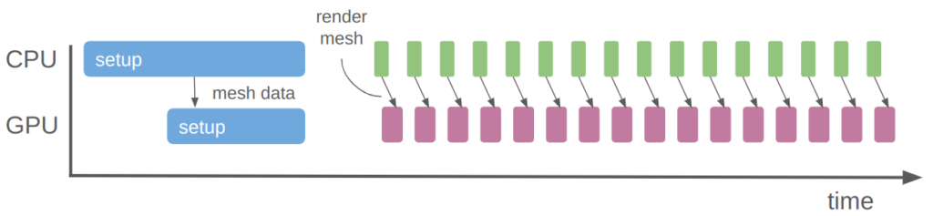
With the rendering we’re doing now, we just update a few small uniforms every frame to change the player position. The mesh data itself is already on the GPU, stored as a vertex buffer object.
So fully specifying the vertex positions over time is both extremely tedious and computationally expensive. What do we do instead?
When a character moves, many of their vertices typically move together. For example, if my character punches, we expect all of the vertices in their clenched fist to together, their forearm arm to follow. Their upper arm follows that, maybe with a bend, etc. Vertices thus tend to be grouped, and we can leverage the grouping for increased efficiency.
Bones
You know how artists sometimes have these wooden figures that they can bend and twist into poses? That’s the industry-standard way to do 3D animation.
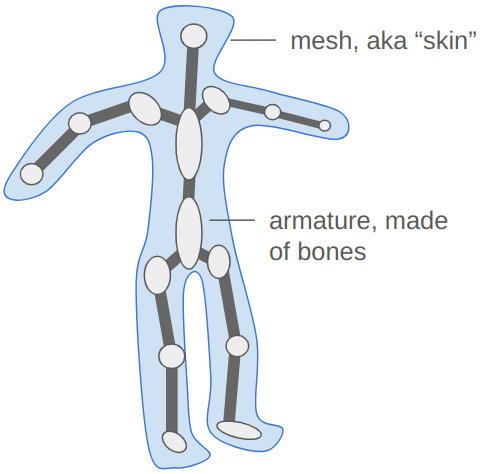
We create an armature, which is a sort of rigid skeleton that we can use to pose the mesh. The armature is made up of rigid entities, bones, which can move around to produce the movement expected in our animation. There are far fewer bones than vertices. We then compute our vertex positions based on the bones positions – a vertex in the character’s fist is going to move with the fist bone.
This approach solves our problems. The bones are much easier to pose and thus build animations out of, and we can continue to send the mesh and necessary bone information to the GPU once at startup, and just send the updated bone poses whenever we render the mesh.
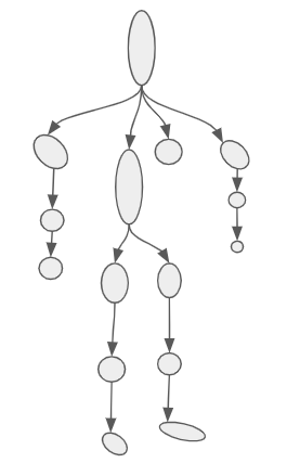
The bones in an armature have a hierarchical structure. Every bone has a single parent and any number of children, except the root bone, which has no parent.
Unlike my oh-so-fancy drawing, bones don’t actually take up space. They are actually just little reference frames. Each bone’s reference frame is given by a transformation \(T\) with respect to its parent. More specifically, \(T\) transforms a point in the bone’s frame to that of its parent.
For example, we can use this transform to get the “location” of a bone. We can get the position of the root bone by transforming the origin of its frame to its parent – the model frame. This is given by \(T_\text{root} \vec{o}\), where \(\vec{o}\) is the origin in homogenous coordinates: \([0,0,0,1]\). Our transforms use 4×4 matrices so that we can get translation, which is ubiquitous in 3D graphics.
Similarly, the position of one of the root bone’s children with transform \(T_\text{c}\) can be obtained by first computing its position in the root bone’s frame, \(T_\text{c} \vec{o}\), and then convert that to the model frame, \(T_\text{root} T_\text{c} \vec{o}\).
The order of operation matters! It is super important. It is what gives us the property that moving a leaf bone only affects that one bone, but moving a bone higher up in the hierarchy affects all child bones. If you ever can’t remember which order it is, and you can’t just quickly test it out in code, try composing two transforms together.
The origin of a bone 4 levels deep is:
\[T_\text{root} T_\text{c1} T_\text{c2} T_\text{c3} T_\text{c4} \vec{o}\]
Let’s call the aggregated transform for bone \(c4\), this product of its ancestors, \(\mathbb{T}_{c4}\).
It is these transformations that we’ll be changing in order to produce animations. Before we get to that, we have to figure out how the vertices move with the bones.
Transforming a Vertex
The vertices are all defined in our mesh. They have positions in model-space.
Each bone has a position (and orientation) in model space, as we’ve already seen.
Let’s consider what happens when we associate a vertex with a bone. That is, we “connect” the vertex to the bone such that, if the bone moves, the vertex moves with it. We expect the vertex to move along in the bone’s local frame:
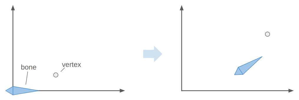
Here the bone both translates to the right and up, and rotates counter-clockwise about 30 degrees. In the image, the vertex does the same.
The image above has the bone starting off at the origin, with its axis aligned with the coordinate axes. This means the vertex is starting off in the bone’s reference frame. To get the vertex into the bone frame (it is originally defined in the model frame), we have to multiply it by \(\mathbb{T}^{-1}\). Intuitively, if \(\mathbb{T} \vec{p}\) takes a point from bone space to model space then the inverse takes a point from model space to bone space.
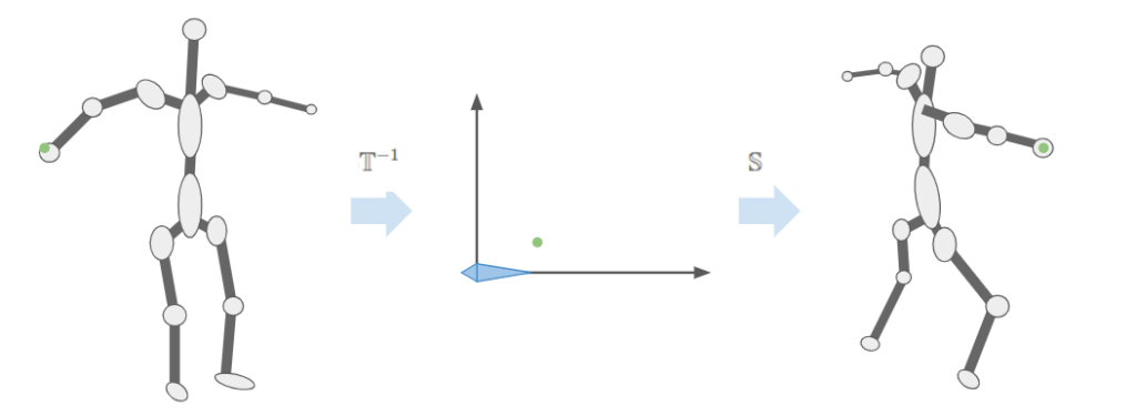
The bone moved. That means it has a new transform relative to its parent, \(S\). Plus, that parent bone may have moved, and so forth. We have to compute a new aggregate bone transform \(\mathbb{S}\). The updated position of the vertex in model space is thus obtained by transforming it from its original model space into bone space with \(\mathbb{T}^{-1}\) and then transforming it back to model space according to the new armature configuration with \(\mathbb{S}\):
\[\vec v’ = \mathbb{S} \mathbb{T}^{-1} \vec v\]
We can visualize this as moving a vertex in the original mesh pose to the bone-relative space, and then transforming it back to model-space based on the new armature pose:
This means we should store \(\mathbb{T}^{-1}\) for each bone in the armature – we’re going to need it a lot. In any given frame we’ll just have to compute \(\mathbb{S}\) by walking down the armature. We then compute \(\mathbb{S} \mathbb{T}^{-1}\) and pass that to our shader to properly pose the model.
Bone Weights
The previous section let us move a vertex associated with a single bone. That works okay for very blocky models composed of rigid segments. For example, a stocky robot or simple car with spinning wheels. Most models are less rigid. Yes, if you punch someone you want the vertices in your fist to follow the hand bone, but as you extend your elbow the vertices near the joint will follow both the bone from the upper arm and the bone from the lower arm. We want a way to allow this to happen.
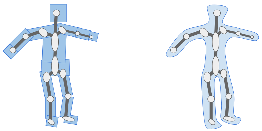
Instead of a vertex being associated with one bone, we allow a vertex to be associated with multiple bones. We have the final vertex combination be a mix of any number of other bones:
\[\vec v’ = \sum_{i=1}^m w^{(i)} \mathbb{S}_i \mathbb{T}_i^{-1} \vec v\]
where the nonnegative weights \(\vec w\) sum to one.
In practice, most vertices are associated with one one or two bones. It is common to allow up to 4 bone associations, simply because that covers most needs and then we can use the 4-dimensional vector types supported by OpenGL.
Data-wise, what this means is:
- In addition to the original mesh data, we also need to provide an armature, which is a hierarchy of bones and their relative transformations.
- We also need to associate each vertex with some set of bones. This is typically done via a
vec4of weights and anivec4of bone indices. We store these alongside the other vertex data. - The vertex data is typically static and can be stored on the graphics card in the vertex array buffer.
- We compute the inverse bone transforms for the original armature pose on startup.
- When we want to render a model, we pose the bones, compute the current bone transforms \(\mathbb{S}\), and then compute and sent \(\mathbb{S} \mathbb{T}^{-1}\) to the shader as a uniform.
Coding it Up
Alright, enough talk. How do we get this implemented?
We start by updating our definition for a vertex. In addition to the position, normal, and texture coordinates, we now also store the bone weights:
struct RiggedVertex {
    glm::vec3 position;   // location
    glm::vec3 normal;     // normal vector
    glm::vec2 tex_coord;  // texture coordinate

    // Up to 4 bones can contribute to a particular vertex
    // Unused bones must have zero weight
    glm::ivec4 bone_ids;
    glm::vec4 bone_weights;
};
This means we have to update how we set up the vertex buffer object:
glGenVertexArrays(1, &(mesh->vao));
glGenBuffers(1, &(mesh->vbo));

glBindVertexArray(mesh->vao);
glBindBuffer(GL_ARRAY_BUFFER, mesh->vbo);
glBufferData(GL_ARRAY_BUFFER, mesh->vertices.size() * sizeof(RiggedVertex),
                              &mesh->vertices[0], GL_STATIC_DRAW);

// vertex positions
glEnableVertexAttribArray(0);
glVertexAttribPointer(0, 3, GL_FLOAT, GL_FALSE, sizeof(RiggedVertex),
                      (void*)offsetof(RiggedVertex, position));
// vertex normals
glEnableVertexAttribArray(1);
glVertexAttribPointer(1, 3, GL_FLOAT, GL_FALSE, sizeof(RiggedVertex),
                      (void*)offsetof(RiggedVertex, normal));
// texture coordinates
glEnableVertexAttribArray(2);
glVertexAttribPointer(2, 2, GL_FLOAT, GL_FALSE, sizeof(RiggedVertex),
                      (void*)offsetof(RiggedVertex, tex_coord));
// bone ids (max 4)
glEnableVertexAttribArray(3);
glVertexAttribIPointer(3, 4, GL_INT, sizeof(RiggedVertex),
                       (void*)offsetof(RiggedVertex, bone_ids));
// bone weights (max 4)
glEnableVertexAttribArray(4);
glVertexAttribPointer(4, 4, GL_FLOAT, GL_FALSE, sizeof(RiggedVertex),
                       (void*)offsetof(RiggedVertex, bone_weights));
Note the use of glVertexAttribIPointer instead of glEnableVertexAttribArray for the bone ids. That problem took me many hours to figure out. It turns out that glVertexAttribPointer accepts integers but has the card interpret them as floating point, which messes everything up it you indent to actually use integers on the shader side.
As far as our shader goes, we are only changing where the vertices are located, not how they are colored. As such, we only need to update our vertex shader (not the fragment shader). The new shader is:
#version 330 core

layout (location = 0) in vec3 aPos;
layout (location = 1) in vec3 aNormal;
layout (location = 2) in vec2 aTexCoord;
layout (location = 3) in ivec4 aBoneIds;
layout (location = 4) in vec4 aBoneWeights;

out vec3 pos_world;
out vec3 normal_world;
out vec2 tex_coords;

const int MAX_BONES = 100;
const int MAX_BONE_INFLUENCE = 4;

uniform mat4 model; // transform from model to world space
uniform mat4 view; // transform from world to view space
uniform mat4 projection; // transform from view space to clip space
uniform mat4 bone_transforms[MAX_BONES]; // S*Tinv for each bone

void main()
{
    // Accumulate the position over the bones, in model space
    vec4 pos_model = vec4(0.0f);
    vec3 normal_model = vec3(0.0f);
    for(int i = 0 ; i < MAX_BONE_INFLUENCE; i++)
    {
        j = aBoneIds[i];
        w = aBoneWeights[j]
        STinv = bone_transforms[j];
        pos_model += w*(STinv*vec4(aPos,1.0f));
        normal_model += w*(mat3(STinv)*aNormal);
    }

    pos_world = vec3(model * pos_model);
    normal_world = mat3(model) * normal_model;
    gl_Position = projection * view * model * pos_model;
    tex_coords = vec2(aTexCoord.x, 1.0 - aTexCoord.y);
}
Note that the normal vector doesn’t get translated, so we only use mat3. The vertice’s texture coordinate is not affected.
Testing it Out
Let’s start with something simple, a 2-triangle, 2-bone system with 5 vertices:
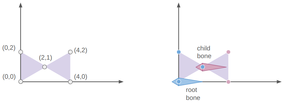
The root bone is at the origin (via the identity transform) and the child bone is at [2,1,0]. The vertices of the left triangle are all associated only with the root bone and the rightmost two vertices are only associated with the child bone.
If we slap on a sin transform for the child bone, we wave the right triangle:
If we instead slap a sin transform on the root bone, we wave both triangles as a rigid unit:
We can apply a sin to both triangles, in which case the motions compose like they do if you bend both your upper and lower arms:
We can build a longer segmented arm and move each segment a bit differently:
Posing a Model
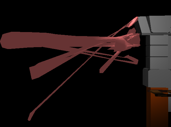
Now that we’ve built up some confidence in our math, we can start posing our model (The low-poly knight by Davmid, available here on Sketchfab) The ideas are exactly the same – we load the model, define some bone transforms, and then use those bone transforms to render its location.
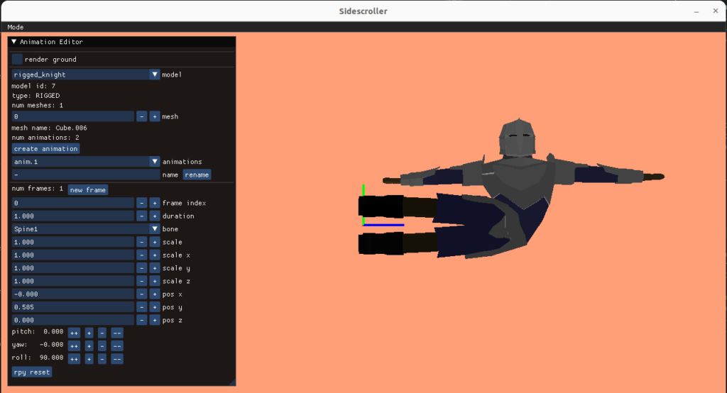
I created an animation editing mode that lets us do this posing. As before, the UI stuff is all done with Dear ImGUI. It lets you select your model, add animations, add frames to those animations, and adjust the bone transforms:
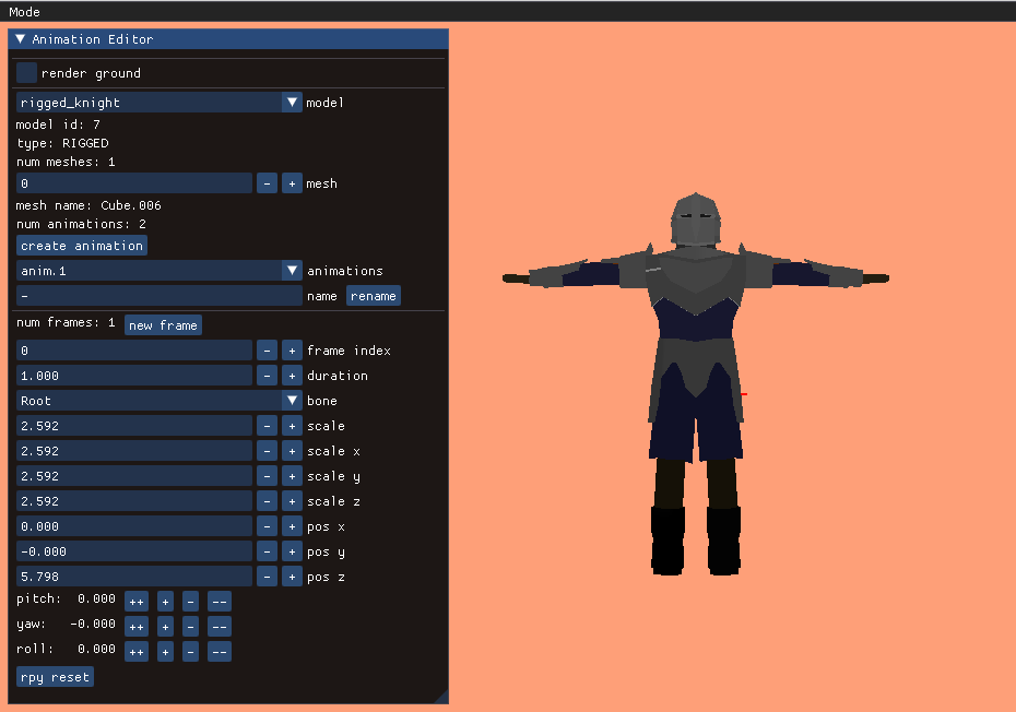
A single frame represents an overall model pose by defining the transformations for each bone:
struct Keyframe {
    f32 duration;
    std::vector<glm::vec3> positions;
    std::vector<glm::quat> orientations;
    std::vector<glm::vec3> scales;
};
The position, orientation, and scale are stored separately, mainly because it is easier to reason about them when they are broken out like this. Later, when we do animation, we’ll have to interpolate between frames, and it is also easier to reason about interpolation between these components rather than between the overall transforms. A bone’s local transform \(S\) is simply the combination of its position, orientation, and scale.
We calculate our fine bone transforms \(\mathbb{S} \mathbb{T}^{-1}\) for our frame and then pass that off to the shader for rendering:
size_t n_bones = mesh->bone_transforms_final.size();
for (size_t i_bone = 0; i_bone < n_bones; i_bone++) {
    glm::vec3 pos = frame.positions[i_bone];
    glm::quat ori = frame.orientations[i_bone];
    glm::vec3 scale = frame.scales[i_bone];

    // Compute the new current transform
    glm::mat4 Sbone = glm::translate(glm::mat4(1.0f), pos);
    Sbone = Sbone * glm::mat4_cast(ori);
    Sbone = glm::scale(Sbone, scale);

    if (mesh->bone_parents[i_bone] >= 0) {
        const glm::mat4& Sparent =
            mesh->bone_transforms_curr[mesh->bone_parents[i_bone]];
        Sbone = Sparent * Sbone;
    }

    mesh->bone_transforms_curr[i_bone] = Sbone;

    glm::mat4 Tinv = mesh->bone_transforms_orig[i_bone];
    mesh->bone_transforms_final[i_bone] = Sbone * Tinv;
}
Conclusion
When you get down to it, the math behind rigged meshes isn’t all too bad. The main idea is that you have bones with transforms relative to their parent bone, and that vertices are associated with a combination of bones. You have to implement rigged meshes that store your bones and vertex weights, need a shader for rigged meshes, and a way to represent your model pose.
This main stuff doesn’t take too long to implement in theory, but this post took me way longer to develop than normal because I wrote a bunch of other supporting code (plus banged my head against the wall when things didn’t initially work – its hard to debug a garbled mess).
Adding my own animation editor meant I probably wanted to save those animations to disk. That meant I probably wanted to save my meshes to disk too, which meant saving the models, textures, and materials. Getting all that set up took time, and its own fair share of debugging. (I’m using a WAD-like data structure like I did for TOOM).
The animation editor also took some work. Dear ImGUI makes writing UI code a lot easier, but adding all of the widgets and restructuring a lot of my code to be able to have separate application modes for things like gameplay and the animation editor simply took time. The largest time suck (and hit to motivation) for a larger project like this is knowing you have to refactor a large chunk of it to make forward progress. Its great to reach the other end though and to have something that makes sense.
We’re all set up with posable models now, so the next step is to render animations. Once that’s possible we’ll be able to tie those animations to the gameplay — have the model walk, jump, and stab accordingly. We’ll then be able to attach other meshes to our models, i.e. a sword to its hand, and tie hitspheres and hurtspheres to the animation, which will form the core of our combat system.