This month continues our foray into the world of DOOM and C software renderers. In the last post, we moved from a blocky, axis-aligned world to general 2D geometry. In this post, not only will we manipulate the 3rd dimension, thereby reaching DOOM-geometry-parity, we will leverage our raycasting approach to unlock something the original DOOM couldn’t do.
Variable Floor and Ceiling Heights
In Wolfenstein 3D, the floors are always at z = 0 and the ceilings are always at z = 1. DOOM could adjust these floor and ceiling heights, and its players were thus able to ascend stairs, traverse next to chasms, and generally enjoy a much richer gaming environment.
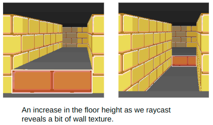
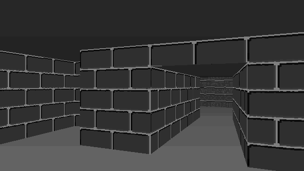
This gif shows the basic z-manipulation I’m talking about:
Here we’re adjusting the floor and ceiling height of our corridor. When we raise the floor, we need to render a wall texture between our floor and the raised corridor floor. When we lower the floor, we need to render a wall texture between the lowered floor and the normal floor on the other end.
Changing the ceiling height can also expose a bit of wall texture:
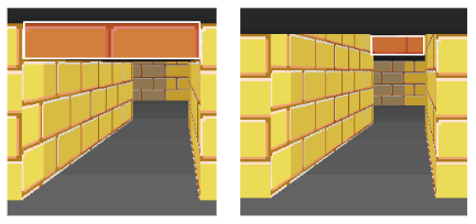
Our renderer has to be able to model these floor sections in order to keep track which of piece of floor has which floor and ceiling height, and we have to keep track of the textures to draw when they are exposed.
Like DOOM, I will denote regions of the map with a particular floor and ceiling height (and later, floor and ceiling textures) to be called a sector. Sectors will naturally be closed polygons in our top-down 2D map.
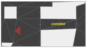
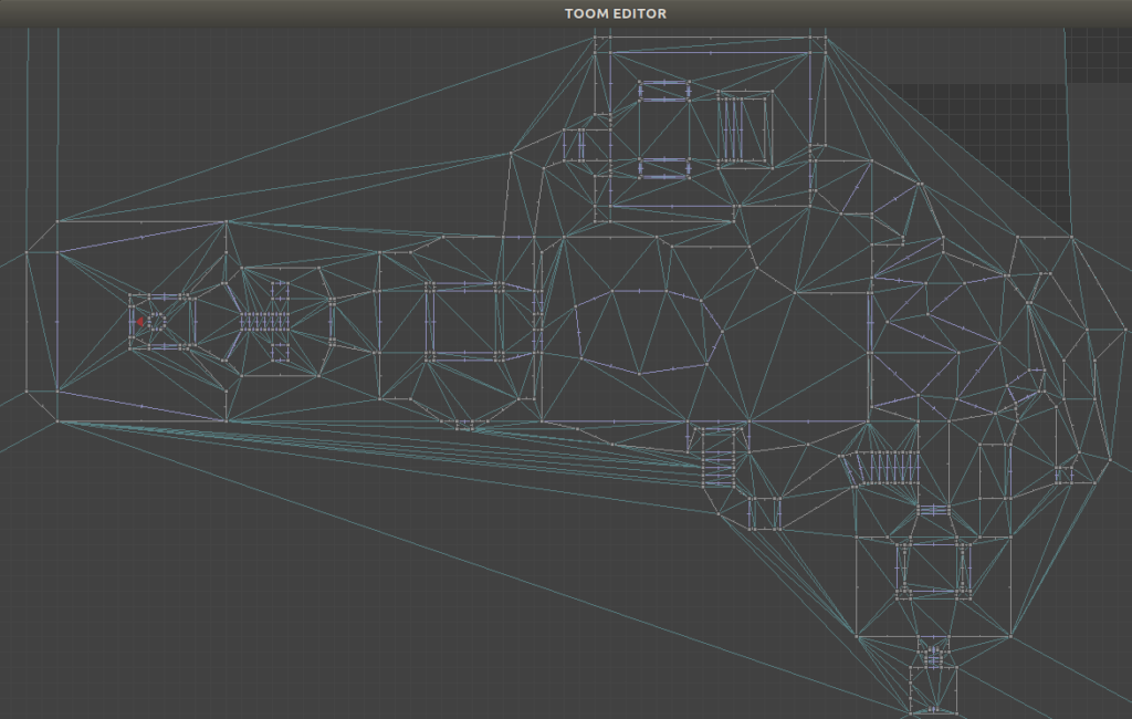
Here you can see a top-down view of the TOOM level editor, showing the same region as rendered above. The red triangle is the camera, which looks toward the right.
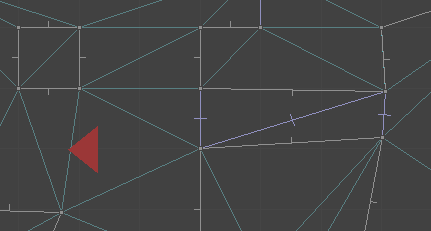
Here is the same shot, filled in a bit to make it easier to interpret:
As covered in the last post, the world is defined using a triangle mesh. Our corridor, for example, is comprised of two triangles. The sector for that corridor must be referenced by the lines along the corridor’s boundary:
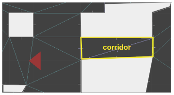
The sector itself just stores the z heights right now. It doesn’t know which edges it corresponds to. Instead, we have the side geometry refer to the sector it should correspond to. This approach is again, very much like DOOM.
We are using a Doubly Connected Edge List (DCEL) to represent our triangle mesh. Edges in a DCEL are bi-directional . If we think of edges as right-handed, and an edge A->B as being on the right-hand side of AB, then we can just have every directed edge at the boundary of a sector keep track of which sector it helps enclose.
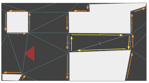
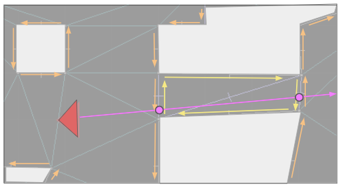
The sides that refer to the corridor are yellow, whereas the sides that refer to the primary sector are orange. When we raycast from the camera down the corridor, we can check for z changes when we traverse over edges where the sector changes. Here we see a raycast with two locations where the sector heights might change:
The data structures for this are pretty simple. A directed edge may have a SideInfo:
struct SideInfo {
    u16 flags;
    u16 sector_id;
    TextureInfo texture_info_lower;
    TextureInfo texture_info_middle;
    TextureInfo texture_info_upper;
};
A SideInfo is simply a struct that contains a lower, middle, and upper texture, the index of the sector to refer to, and some flags. Right now, the only flag I use is one to determine whether a wall is passable, and if so, we can avoid rendering the middle texture.
The TextureInfo entry is pretty simple as well:
struct TextureInfo {
    u16 texture_id; // Index in the texture atlas
    i16 x_offset;   // Texture x offset
    i16 y_offset;   // Texture y offset
};
And Sectors are just basic data as well:
struct Sector
{
    u16 flags;
    f32 z_floor;
    f32 z_ceil;
};
Raycasting with Varying Heights
With these data structures in-hand, rendering becomes a little more complicated. We continue to cast our ray out, as before. Now, however, we need to keep track of how much we’ve already drawn.
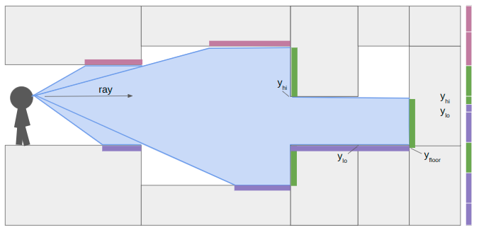
To illustrate, let’s look at a horizontal cross-section of geometry:
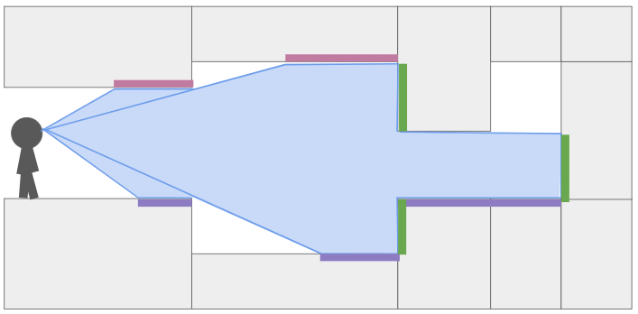
Here I have drawn the area swept out as we cast a single ray to the right, down a single pixel-column. The light purple boxes show all of the regions in our field-of-view where we need to render ceiling pixels, the dark purple boxes show where we need to render floor pixels, and the green boxes show where we need to render wall pixels.
When we start raycasting, we start having not drawn any pixels. The bounds on where we can draw contains the whole vertical pixel column, between zero and the number of pixels:
\[y_\text{lo} = 0 \qquad y_\text{hi} = \text{SCREEN_SIZE_Y}\]
We start to traverse the mesh, and hit our first sector change:
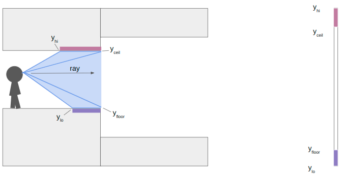
At this point we calculate the y-location (i.e., location in the vertical pixel column) of the ends of the floor and ceiling. We render the floor and ceiling into our pixel column. We’re already pretty used to this trigonometry by now.
\[\begin{aligned} y_\text{ceil} & = \frac{\text{SCREEN_SIZE_Y}}{2} + \gamma \left( z_\text{ceil} – z_\text{camera} \right) \\ y_\text{floor} & = \frac{\text{SCREEN_SIZE_Y}}{2} + \gamma \left( z_\text{floor} – z_\text{camera} \right)\end{aligned}\]
where
\[\gamma = \frac{\text{SCREEN_SIZE_Y}}{\text{y field of view}} \cdot \frac{\text{cam length}}{\text{ray length}}\]
The y yield of view is how many units up the camera views for every unit we raycast outward. I’m using about 0.84. The camera length is close to 1, and adjusts for the fact that our screen is flat and not curved, so rays travelling left or right of center have to have the length adjusted. Other than that, its just a function of the heights and how far our ray has traveled.
In this case, the next sector has an increase in the ceiling height and a decrease in the floor height. That means we do not have any local wall textures to render. We set \(y_\text{lo} = y_\text{floor}\) and \(y_\text{hi} = y_\text{ceil}\) and keep on raycasting:
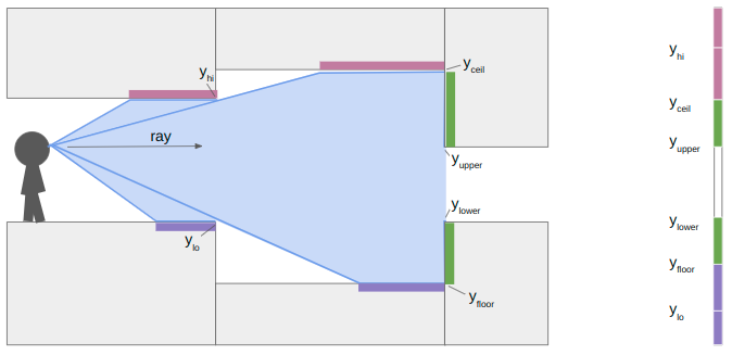
At the next sector transition, we once again compute \(y_\text{floor}\) and \(y_\text{ceil}\). This time, however, the ceiling drops and the floor rises, so we also have wall segments to render. We compute their pixel extents in the same way:
\[\begin{aligned} y_\text{upper} & = \frac{\text{SCREEN_SIZE_Y}}{2} + \gamma \left( z_\text{upper} – z_\text{camera} \right) \\ y_\text{lower} & = \frac{\text{SCREEN_SIZE_Y}}{2} + \gamma \left( z_\text{lower} – z_\text{camera} \right)\end{aligned}\]
where \(z_\text{upper}\) and \(z_\text{lower}\) are the new sector ceiling and floor heights, respectively.
When we continue our raycast, we find that the next sector transition only increases the ceiling height. The new \(y_\text{floor}\) is greater than \(y_\text{lo}\), so we render the patch of floor. The new \(y_\text{ceil}\) is not any lower than our current \(y_\text{hi}\), due to the ceiling being parallel to our camera view, so we don’t need to render anything there.
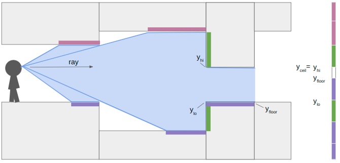
We finally proceed and hit a closed sector. We render the last bit of floor and then render its center texture:
So that’s how the renderer works when you have variable z heights and upper, middle, and lower textures. Each raycast has to do more work to determine what to draw, and it keeps track of where it is within its y pixel bounds to make sure we don’t mistakenly draw something on top of what we’ve already rendered.
Rendering Textures
In this previous blog post, I covered sprites, and how they use the DOOM picture format. In short, sprites like monsters are stored in vertical pixel strips. Why? Because when we render the vertical portions of the world, we’re rendering convenient vertical sections of these sprites. The vertical orientation forms a right-triangle, which makes the math of figuring out which pixel to draw more efficient. DOOM uses the same format for wall textures (both upper and lower). I ended up doing the same thing.
So, wall textures are the same as sprites. What about horizontal textures? We’d like to draw textures on our ceilings and floors too:
(Yeah, these don’t fit thematically. I haven’t loaded my own floor and ceiling textures yet. These just come from DOOM.)
We can again leverage our previous work to figure out how to draw floor and ceiling textures. Unlike the vertically-oriented wall textures, these “flat” textures are most efficiently drawn horizontally across the screen. As such, in DOOM they are called flats.
Our render is most adept at rendering things vertically. It works on one pixel column at a time. So how do we hope to render anything horizontally?
Well, the raycasts start with the leftmost pixel column and then work their way to the right. I keep track of active spans, which are horizontal sections of the screen that need to eventually be rendered with a single flat at a single floor height. Whenever we need to start a new span, we close out the previous one and render it.
The gif above shows how the renderer produces a scene. We draw vertical sections as we raycast, but start/maintain horizontal spans that only get rendered (1) when another span in the same y-coordinate starts or (2) we are done raycasting.
Each active span contains all of the information needed to render it efficienctly, once it needs to be rendered:
struct ActiveSpanData {
    // Location of ray_dir_lo's intersection with the ground.
    common::Vec2f hit;
    // Shift 'hit' by one pix column moved toward hi's intersection.
    common::Vec2f step;
    u16 sector_id;
    u16 flat_id;
    bool is_active;
    // The camera x pixel index where this span starts.
    int x_start;
    // The most recent camera x pixel where this span currently ends.
    int x_end;
};
We can do the computation work of calculating the hit and step values when we first create the span. We set x_start at that time, and initially set x_end to the same value. If we go to render the same sector in the same location in the next column, we increment x_end.
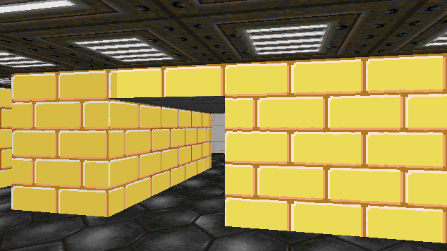
Colors and Light Levels
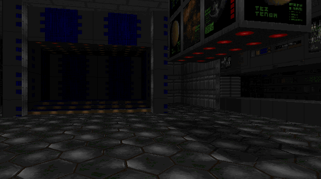
You may have noticed that these images get darker the further we’re looking. This is an intentional effect from DOOM that enhances the sense of depth.
This is easiest to see without the floor textures:
Conceptually, this is really simple. Render pixels darker when they are further away.
The light level of a pixel column drops off as the raycast distance increases. Or rather, the darkness level increases with the raycast distance.
Pixel values are written to the screen as RGB values. How does one take an RGB value and make it darker? Well, white is 0xFFFFFF and black is 0x000000, so the simplest way is to decrease each channel by some percentage. To do it “more correctly”, you can convert your RGB color into the Lab colorspace, reduce its lightness, and then convert it back. That is an expensive operation.
The original DOOM didn’t have access to RGB values. Or rather, it didn’t have access to all of them. According to the DOOM Black Book, PC video games of the 90s had 320×200 resolution with 1 byte per pixel drawn from a 256-color palette. This meant that programmers could set the 256 colors in the palette, and drawing a pixel to the screen effectively meant indexing into this palette by setting a 1-byte pixel index rather than a full RGB value.
So how does one change a pixel’s brightness?
The DOOM developers precomputed mappings from pixel values at full brightness to pixel values at reduced brightness. There were many such colormaps, 32 that were computed for all light levels from 100% brightness all the way down to 0%. There were even some additional colormaps, such as an inverted colormap used when the player becomes invulnerable:
All wall textures and flats store pixel indices rather than RGB values. These pixel indices pass through the chosen colormap and then index into the palette to get the RGB value. In the original DOOM system, indexing into the palette was done for you by the video card. I’ll be doing it myself here.
u8 palette_index = patch.post_data[column_offset];
palette_index = colormap.map[palette_index];
u32 abgr = *(u32*)(palette.colors + 3 * palette_index) | 0xFF000000;
The palette stores sequential BGR values, so we just grab the section we need and then overwrite the FF for the alpha channel.
struct Palette {
    u8 rgbs[768];
};

struct Colormap {
    u8 map[256];
};
As a final note, there is one additional lighting effect that helps make the map more legible. Like the trick used in Wolfenstein, walls closer to being x-aligned are drawn 1 point brighter than normal, and walls closer to being y-aligned are drawn 1 point darker than normal. Furthermore, each sector has its own baseline light level. This lets the map creator make some areas naturally darker, and allows for some nice floor shadow effects:
DOOM Levels
Ah, that last image gave it away. The geometry changes and lighting changes now bring us more-or-less to parity with the original DOOM. We can load and traverse the original DOOM levels!
This rendering is done using the raycasting method, via our DCEL, rather than using DOOM’s BSP. This means we can totally avoid loading SEGS, SSECTORS, NODES, and the BLOCKMAP.
E1M1 loaded into the TOOM editor.
Work was required to be able to load the geometry into our DCEL correctly. Mainly in being able to properly flip mesh edges in order to be able to produce edges that match the map geometry, and then constrain them. I might cover that in a future post.
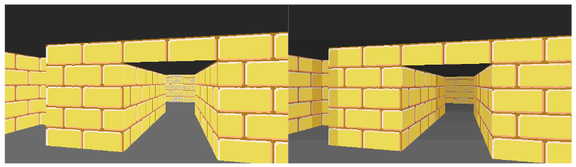
Portals
Okay, we’ve reached geometric parity with DOOM. Is there something this DCEL approach can do that DOOM cannot?
So how does that work?
When we raycast or when the player walks around, we traverse between faces in our triangle mesh. We can create a portal by linking two edges in the triangle mesh and adding the necessary logic such that, when traversed, we come out the linked edge instead.
Below we see the top-down view of the portal setup playing out. The red triangle shows the player camera and its approximate view cone.
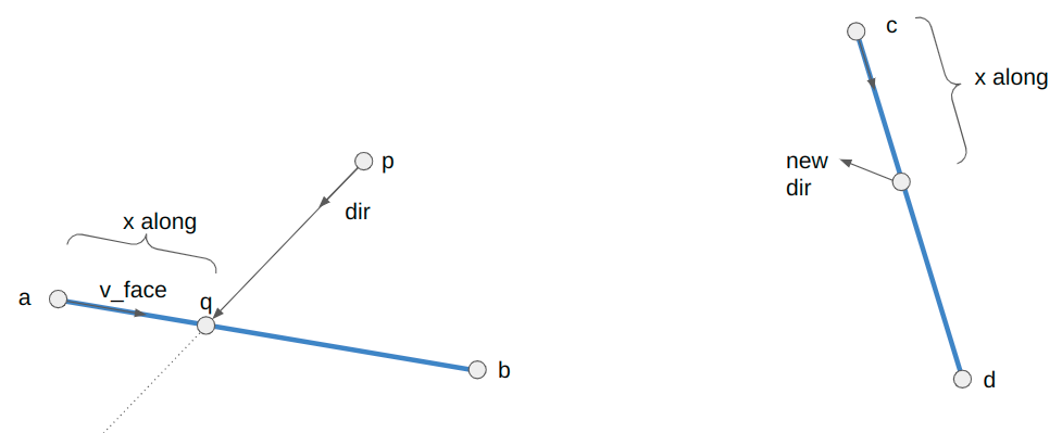
The player movement for when we traverse a portal is:
// Suppose we are crossing the line segment AB from pos to pos_next,
// where pos_next now lies on AB.
Vec2f v_face = b - a;
// Calculate where along the segment we intersected.
f32 v_face_len = Norm(v_face);
f32 x_along_texture = v_face_len - Norm(pos_next - a);
// Update our quarter edge using the destination quarter edge
// stored in the side info.
camera_state->qe = mesh.Tor(side_info->qe_portal);
// The vector along the new face is
Vec2f c = mesh.GetVertex(side_info->qe_portal);
Vec2f d = mesh.GetVertex(mesh.Sym(side_info->qe_portal));
Vec2f cd = d - c;
cd = Normalize(cd);
// Our new position is:
camera_state->pos = c + x_along_texture * cd;
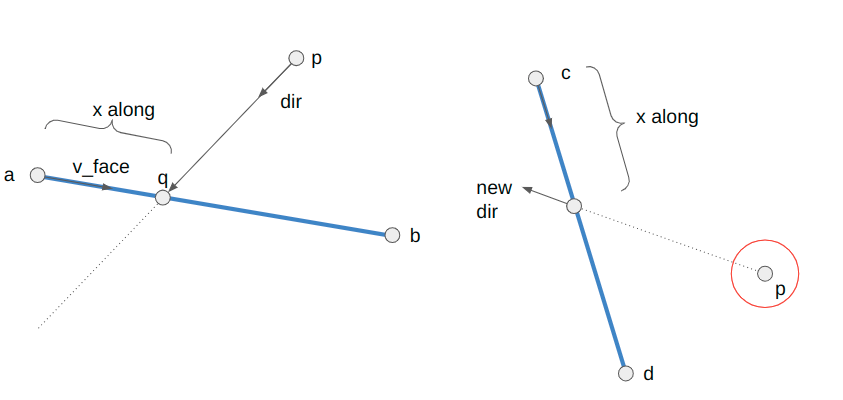
f32 angle_ab = std::atan2(v_face.y, v_face.x);
f32 angle_cd = std::atan2(cd.y, cd.x);
f32 angle_rot = CounterClockwiseAngleDistance(angle_ab, angle_cd) + M_PI;
f32 cos_rot = std::cos(angle_rot);
f32 sin_rot = std::sin(angle_rot);
// Now to get the new direction, we need to rotate out of the new face
dir = {cos_rot * dir.x - sin_rot * dir.y,
sin_rot * dir.x + cos_rot * dir.y};
// We also need to rotate our speed
vel = {cos_rot * vel.x - sin_rot * vel.y,
sin_rot * vel.x + cos_rot * vel.y};Geometrically, we are figuring out the rotation angle between our portals (which could be precomputed) and then rotating our movement direction and speed when we traverse.
Note that the +pi term compensates for the fact that the destination portal side is oriented 180 degrees with respect to the source portal side.
When we raycast through portals, we have properly account for any height changes on the receiving sector. We want to view the other side as if we were the appropriate height:
camera_z += (sector_dst->z_floor - sector_src->z_floor);
There is a bit of extra bookkeeping we have to do with portals – namely that for flats to render correctly we have to update the camera position to the place it would be as if the portal did not exist and we were peering toward our destination:
We then have to recompute some of the vectors used to create spans. This is all because flats are rendered on a fixed grid, and we compute where we are in that grid based on the camera location. We have to fake the camera being in the proper location “behind” where the portal surface is. Please take a look at the source code for the nitty-gritty.
There is a lot of neat gamemap stuff that one can do with portals and the non-Euclidean geometry they unlock. Some of it is more blatant, like the first portal, and some of it can be quite subtle, like a hallways that is shorter or longer than expected.
Conclusion
This blog post covered adding variable z heights for floors and ceilings, which then required being able to render wall sections revealed at floor or ceiling height changes. We rendered those vertically, because that is most efficient. We then figured out a way to render horizontal textures too, which were most efficient to render in horizontal strips. We added some lighting effects. We then had everything we needed to represent the original DOOM level geometry. We concluded with an overview of portals – sides in our mesh that are linked together such that crossing one results in you exiting out the other.
I made the code for TOOM and TOOMED available in separate repos. TOOM is the “game”, written in pure C without graphics libraries. TOOMED is the TOOM Editor, written in C++. It basically doesn’t use graphics libraries either, but it does use Dear ImGui with an accelerated backend, as well as have more liberal data structures for easier manipulation of game data and assets.
That’s more or less it for TOOM, for now. There are a few things the renderer doesn’t support that DOOM has, such as animated nukage, pickups, or proper handling for partially-transparent walls. There obviously isn’t any gameplay. No shooting or doors or anything like that. Those things are neat, of course, but I feel like I already understand how they work, and it’d just be pretty tedious work for me to get TOOM running with all that. Maybe I’ll do it, but for now I’m thinking I’ll be turning to other interests. Thanks for reading!
A Note on Efficiency
One of the reasons that this TOOM project interested me in the first place was the promise that I might learn how to program something “for real” and really have to care about performance. I admire folks like Casey Muratori and Jonathan Blow who ardently advocate for efficient programming, and that software engineers should understand what goes on under modern abstractions.
I tried to keep TOOM running at over 30fps. I was able to track this using a profiling technique covered by Casey in his performance-aware programming class.
For a moderately-expensive scene in E1M1, TOOM clocks in at about 130fps:
Frame dt:   28.9459ms
Total time: 7.6722ms, 130.3 fps (CPU freq 1992267920)
  Poll:   32405 (0.21%)
  Tick:   7097 (0.05%)
  Render: 15245367 (99.74%)
  DKBS:   249 (0.00%)
As we can see, 99.74% of the time is spent rendering. That is to be expected, since that is where all the work is.
Here the frame dt is the 30Hz enforced by my monitor, because SDL is syncing to my monitor refresh rate. This is with a 640 x 320 window, which is double the resolution of the original DOOM. Yes, this is like 30 years after DOOM came out, but I am nevertheless quite happy with these results.
TOOMED, however, is a bit slower:
Total time: 35.2314ms (CPU freq 1991906430)
  GetRightHandedness  [ 25801]:     792837 (1.13%)
  RenderPatchColumn   [  1760]:    8381240 (11.94%)
  RenderSpan          [   318]:    3498674 (4.99%)
  Raycast             [   640]:   35425448 (50.48%, 72.23% w/children)
  Raycast_EdgeChecks  [  8600]:    2322161 (3.31%, 4.43% w/children)
  Raycast_WithValidSideInfo[  2720]:    3599229 (5.13%, 17.32% w/children)
  RenderScene         [     1]:     146851 (0.21%, 77.17% w/children)
It takes about 4.6x as long for TOOMED to render the same scene, giving it a frame rate of about 28fps. That is not great.
Yes, TOOMED is doing a little more, in that it also renders the top-down GUI. However, that GUI stuff is pretty negligible. I believe the real culprit here more-or-less boils down to two things: memory layout and dictionary lookups.
In TOOM, everything is accessed directly in the binary save file. Entries are all nicely indexed and can be quickly accessed. In TOOMED, since we’re editing things, we store them in std::vectors and std::maps, which results in disparate structures spread out in different locations. In many cases it simply takes more effort for the CPU to get access to what it needs. Furthermore, dictionary lookups, while being O(1), are still doing more work than a simple array access. The delta here, 4.6x, is pretty substantial, and this is the sort of takeaway that I think serious gamedev folk mean when they say paying attention to your data structures and memory strategies matters.
As a final fun learning point, my raycast method was initially recursive. That is, every time we step our ray and transfer over a triangle edge, I’d recurse down in order to process the next triangle step. I figured that this would make it easier to later back-track and render things like monsters or item pickups. However, TOOMED was running _extremely_ slowly, around 70ms per frame. Changing from recursion to a loop cut that time in about half. Its the same amount of work, theoretically, only now we don’t have to make a bunch of copies every time we push to the stack.