I am having fun figuring out how to write a 2D sidescroller from scratch, with 3D graphics. I’ve covered how posing and animating those skeletal meshes works. This post extends that work with inverse kinematics, which allows for the automatic placement of hands or feet at specific locations.
This wonderful low-poly knight comes from Davmid at SketchFab.
Some Recap
A character’s pose is defined by the transforms of their skeleton. A skeleton is made up of bones, where each bone is translated, offset, and scaled with respect to a parent bone.
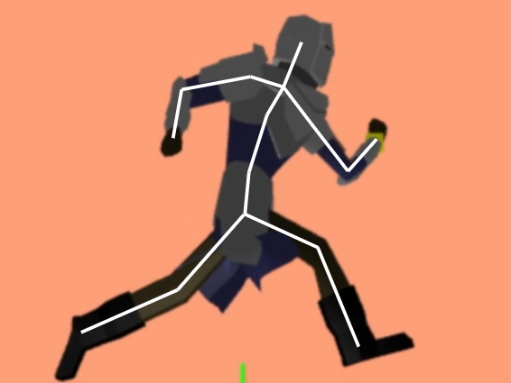
The \(i\)th bone’s transform is given by:
\[\begin{aligned}\boldsymbol{T}_i &= \text{trans}(\boldsymbol{\Delta}_i) \cdot \text{rot}(\boldsymbol{q}_i) \cdot \text{scale}(\boldsymbol{s}) \\ &= \begin{bmatrix}1 & 0 & 0 & \Delta_x \\ 0 & 1 & 0 & \Delta_y \\ 0 & 0 & 1 & \Delta_z \\ 0 & 0 & 0 & 1\end{bmatrix} \cdot \begin{bmatrix} 1 – 2(q_y^2+q_z^2) & 2(q_x q_y – q_w q_z) & 2(q_x q_z + q_w q_y) & 0 \\ 2(q_x q_y + q_w q_z) & 1 – 2(q_x^2 + q_z^2) & 2(q_y q_z – q_w q_x) & 0 \\ 2(q_x q_z – q_w q_y) & 2(q_y q_z – q_w q_x) & 1 – 2(q_x^2 + q_y^2) & 0 \\ 0 & 0 & 0 & 1\end{bmatrix} \cdot \begin{bmatrix}s_x & 0 & 0 & 1 \\ 0 & s_y & 0 & 1 \\ 0 & 0 & s_z & 1 \\ 0 & 0 & 0 & 1\end{bmatrix}\end{aligned}\]
where \(\boldsymbol{\Delta}_i\) is its translation vector, \(\boldsymbol{q}_i\) is its orientation quaternion, and \(\boldsymbol{s}\) is its scaling vector. The transforms are \(4\times 4\) matrices because we’re using homogeneous coordinates such that we can support translations. A 3D position is recovered by dividing each of the first three entries by the fourth entry.
The resulting transform converts homogeneous locations in the bone’s local coordinate frame into the coordinate frame of its parent:
\[\boldsymbol{p}_{\text{parent}(i)} = \boldsymbol{T}_i \boldsymbol{p}_i\]
We can keep on applying these transforms all the way to the root bone to transform the bone into the root coordinate frame:
\[\boldsymbol{p}_{\text{root}} = \boldsymbol{T}_{\text{root}} \cdots \boldsymbol{T}_{\text{parent}(\text{parent}(i))} \boldsymbol{T}_{\text{parent}(i)} \boldsymbol{T}_i \boldsymbol{p}_i = \mathbb{T}_i \boldsymbol{p}_i\]
This aggregate transform \(\mathbb{T}_i\) ends up being very useful. If we have a mesh vertex \(\boldsymbol{v}\) defined in mesh space (with respect to the root bone), we can transform it to the \(i\)th bone’s frame via \(\mathbb{S}^{-1}_i \boldsymbol{v}\) according to the aggregate transform of the original skeleton pose and then transform it back into mesh space via \(\mathbb{T}_i \mathbb{S}^{-1}_i \boldsymbol{v}\). That gives us the vertex’s new location according to the current pose.
The Problem
We can define keyframes and interpolate between them to get some nice animations. However, the keyframes are defined in mesh space, and have no way to react to the world around them. If we have a run animation, the player’s foot will always be placed in the same location, regardless of the ground height. If the animation has the player’s arms extend to grab a bar, it can be very easy for the player’s position to be off and the hands not quite be where the edge is.
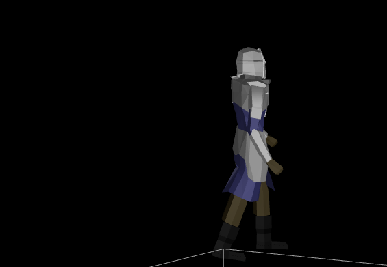
Here one foot is hovering in the air and the other is sticking into the ground.
The animation system we have thus far produces hand and foot positions with forward kinematics — the positions are based on the successive application of transforms based on bones in the skeleton hierarchy. We want to do the opposite — find the transforms needed such that an end effector like a hand or a foot ends up where we want it to be.
There are several common ways to formulate this problem. I am going to avoid heuristic approaches like cyclic coordinate descent and FABRIK. This method will be closed-form rather than iterative.
Instead of supporting any number of bones, I will stick to 2-bone systems. For example, placing a wrist by moving an upper an lower arm, or placing a foot by moving an upper and lower leg.
Finally, as is typical, I will only allow rotations. We don’t want our bones to stretch or displace in order to reach their targets.
Our inverse kinematic problem thus reasons about four 3D vectors:
- a fixed hip position \(\boldsymbol{a}\)
- an initial knee position \(\boldsymbol{b}\)
- an initial foot position \(\boldsymbol{c}\)
- a target foot position \(\boldsymbol{t}\)
Our job is to adjust the rotation transform of the hip and knee bones such that the foot ends up as close as possible to the target position.
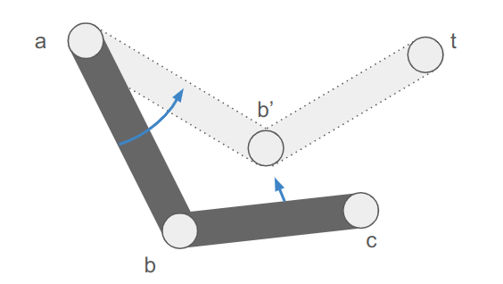
The image makes it easy to forget that this is all happening in 3D space.
Working it Out
We are going to break this down into two parts. First we will find the final knee and foot positions \(\boldsymbol{b}’\) and \(\boldsymbol{c}’\). Then we’ll adjust the bone orientations to achieve those positions.
Finding the New Positions
There are three cases:
- we can reach the target location and \(\boldsymbol{c}’ = \boldsymbol{t}\)
- the bone segments aren’t long enough to reach the target location
- the bone segments are too long to reach the target location
Let’s denote the segment lengths as \(\ell_{ab}\) and \(\ell_{bc}\), and additionally compute the distance between \(\boldsymbol{a}\) and \(\boldsymbol{t}\):
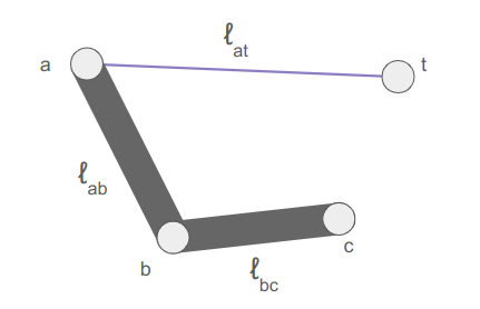
The target is too close if \(\ell_{at} < |\ell_{ab} – \ell_{bc}|\). When that happens, we extend the longer segment toward the target and the other segment away.
The target is too far if \(\ell_{at} > \ell_{ab} + \ell_{bc}\). When that happens, we extend the segments directly toward the target, to maximum extension.
The remaining, more interesting case is when the target can be reached exactly, and we know \(\boldsymbol{c}’ = \boldsymbol{t}\). In that case we still have to figure out where the knee \(\boldsymbol{b}’\) ends up.
The final knee position will lie on a circle that is the intersection of two spheres: the sphere of radius \(\ell_{ab}\) centered at \(\boldsymbol{a}\) and the sphere of radius \(\ell_{bc}\) centered at \(\boldsymbol{t}\):
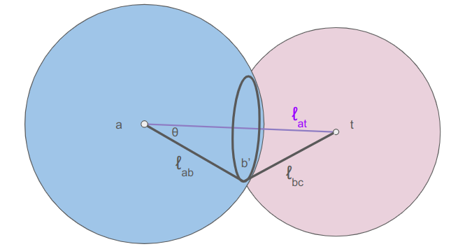
We can calculate \(\theta\) from the law of cosines:
\[\cos \theta = \frac{\ell_{bc}^2 – \ell_{ab}^2 – \ell_{at}^2}{-2 \ell_{ab} \ell_{at}} \]
The radius of the circle that \(\boldsymbol{b}’\) lies on is:
\[r = \ell_{ab} \sin \theta = \ell_{ab} \sqrt{1 – \cos^2 \theta}\]
The center of the circle is then
\[\boldsymbol{m} = \boldsymbol{a} \> – \> \ell_{ab} \cos \theta \hat{\boldsymbol{n}}\]
where \(\hat{\boldsymbol{n}}\) is the unit vector from \(\boldsymbol{t}\) to \(\boldsymbol{a}\).
We can place the knee anywhere we want on this circle using some unit vector \(\hat{\boldsymbol{u}}\) perpendicular to \(\hat{\boldsymbol{n}}\):
\[\boldsymbol{b}’ = \boldsymbol{m} + r \hat{\boldsymbol{u}}\]
For the inverse kinematics to look nice, I want to move the knee as little as possible. As such, let’s try to keep \(\hat{\boldsymbol{u}}\) close to the current knee position:
\[\begin{aligned}\boldsymbol{v} &= \boldsymbol{b} \> – \boldsymbol{m} \\ \boldsymbol{u} &= \boldsymbol{v} \> – (\boldsymbol{v} \cdot \hat{\boldsymbol{n}}) \hat{\boldsymbol{n}} \\ \hat{\boldsymbol{u}} &= \text{normalize}(\boldsymbol{u}) \end{aligned}\]
We can implement this in code as follows:
f32 len_ab = glm::length(b - a);
f32 len_bc = glm::length(c - b);
f32 len_at = glm::length(t - a);

// Unit vector from t to a.
glm::vec3 n = (a - t) / len_at;
if (len_at < 1e-3f) {
    n = glm::vec3(1.0f, 0.0f, 0.0f);
}

bool reached_target = false;
glm::vec3 b_final, c_final;  // The final positions of the knee and foot.
if (len_at < std::abs(len_ab - len_bc)) {
    // The target is too close.
    // Extend the longer appendage toward it and the other away.
    int sign = (len_ab > len_bc) ? 1 : -1;
    b_final = a - sign * len_ab * n;
    c_final = b_final + sign * len_bc * n;

} else if (len_at <= len_ab + len_bc) {
    // The target is reachable
    reached_target = true;
    c_final = t;

    // The final knee position b_final will lie on a circle that is the intersection of two
    // spheres: the sphere of radius len_ab centered at a and the sphere of radius len_bc
    // centered at t.

    // Cosine of the angle t - a - b_final
    f32 cos_theta =
        (len_bc * len_bc - len_ab * len_ab - len_at * len_at) / (-2 * len_ab * len_at);
    f32 sin_theta = std::sqrt(1.0 - cos_theta * cos_theta);

    // Radius of the circle that b_final must lie on.
    f32 r = len_ab * sin_theta;

    // The center of the circle that b_final must lie on.
    glm::vec3 m = a - len_ab * cos_theta * n;

    // Unit vector perpendicular to n and pointing at b from m.
    // If b and m are coincident, we default to any old vector perpendicular to n.
    glm::vec3 u = GetPerpendicularUnitVector(n, b - m);

    // Compute the new knee position.
    b_final = m + r * u;

} else {
    // The target is too far.
    // Reach out toward it to max extension.
    b_final = a - len_ab * n;
    c_final = b_final - len_bc * n;
}
Adjusting the Orientations
Now that we have the updated knee and foot positions, we need to adjust the bone transforms to rotate the segments to match them.
The bone transforms are all defined relative to their parents. Let our end effector (the hand or foot) be associated with bone \(i\), its parent (the elbow or knee) be associated with bone \(j\), and its parent (the hip or shoulder) be associated with bone \(k\). We should already have the aggregate transforms for these bones computed for the existing pose.
First we’ll rotate bone \(k\) to point toward \(\boldsymbol{b}’\) instead of \(\boldsymbol{b}\). We need to calculate both positions in the bone’s local frame:
\[\begin{aligned}\boldsymbol{b}_\text{local} &= \mathbb{T}_k^{-1} \> \boldsymbol{b} \\ \boldsymbol{b}’_\text{local} &= \mathbb{T}_k^{-1} \> \boldsymbol{b}’ \end{aligned}\]
We then normalize these vectors and find the rotation that between them. A minimum rotation between two unit vectors \(\hat{\boldsymbol{u}}\) and \(\hat{\boldsymbol{v}}\) has an axis of rotation:
\[\boldsymbol{a} = \hat{\boldsymbol{u}} \times \hat{\boldsymbol{v}}\]
and a rotation angle:
\[\theta = \cos^{-1}\left(\hat{\boldsymbol{u}} \cdot \hat{\boldsymbol{v}}\right)\]
// Find the minimum rotation between the two given unit vectors.
// If the vectors are sufficiently similar, return the unit quaternion.
glm::quat GetRotationBetween(const glm::vec3& u, const glm::vec3& v, const f32 eps = 1e-3f) {
    glm::vec3 axis = glm::cross(u, v);
    f32 len_axis = glm::length(axis);
    if (len_axis < eps) {
        return glm::quat(0.0f, 0.0f, 0.0f, 1.0f);
    }

    axis /= len_axis;
    f32 angle = std::acos(glm::dot(u, v));
    return glm::angleAxis(angle, axis);
}
We then adjust the orientation of bone \(k\) using this axis and angle to get an updated transform, \(\boldsymbol{T}_k’\). We then propagate that effect down to the child transforms.
We do the same thing with bone \(j\), using the updated transform. The code for this is:
glm::mat4 iTTk = glm::inverse(TTk);
glm::vec3 local_currt = glm::normalize(To3d(iTTk * glm::vec4(b, 1.0f)));
glm::vec3 local_final = glm::normalize(To3d(iTTk * glm::vec4(b_final, 1.0f)));
frame->orientations[grandparent_bone] =
    frame->orientations[grandparent_bone] * GetRotationBetween(local_currt, local_final);

(*bone_transforms)[grandparent_bone] =
    (*bone_transforms)[grandgrandparent_bone] * CalcTransform(*frame, grandparent_bone);
(*bone_transforms)[parent_bone] =
    (*bone_transforms)[grandparent_bone] * CalcTransform(*frame, parent_bone);

// Do the same with the next bone.
glm::mat4 TTj_new = (*bone_transforms)[parent_bone];
local_currt = glm::normalize(To3d(glm::inverse(TTj) * glm::vec4(c, 1.0f)));
local_final = glm::normalize(To3d(glm::inverse(TTj_new) * glm::vec4(c_final, 1.0f)));
frame->orientations[parent_bone] =
    frame->orientations[parent_bone] * GetRotationBetween(local_currt, local_final);
Conclusion
This approach to inverse kinematics is efficient and effective. I’ve been using it to refine various action states, such as placing hands and feet onto ladder rungs:
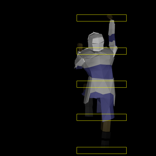
It works pretty well when the hand or foot doesn’t have to be adjusted all that much. For larger deltas it can end up picking some weird rotations because it does not have any notion of maximum joint angles. I could add that, of course, at the expense of complexity.
Its really nice to be able to figure something out like this from the basic math foundations. There is something quite satisfying about being able to lay out the problem formulation and then systematically work through it.
Cheers!