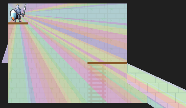
A debug view showing shadow cast segments from the vantage point of the actor.
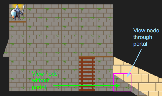
Last month we covered the unified action system, in which we built some basic things players can do with their heroes, and set the stage for fancier futures and actions for enemy agents. The most significant action was moving, which was built based on a GridView of what the actor sees from their current vantage point. As noted in that post, we eventually wanted to expand the grid view to include edge information, such as thin little walls and platforms, but also portals that act as non-Euclidean connections to other parts of the map.
Here we have a simple two-tile room with a loop-back portal on either end. The result – the hero can see a bunch of versions of themselves!
In the last post, I said I’d be adding other entities in and adding more actions, but I decided that the map representation was so fundamental that prioritizing getting these portals in was more important. Any changes there would affect most other systems, so I wanted to get that done first.
Grid Representation
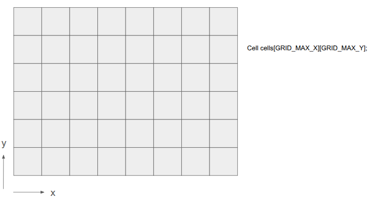
Prior to this change, the underlying level geometry representation, the Grid, was just a 2D array of cells:
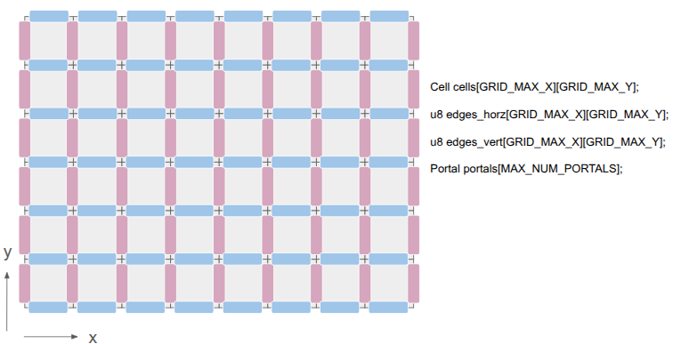
After this change, I wanted to represent both the cells as well as the edges between them:
This was achieved by adding two additional 2D arrays, one for the horizontal edges and one for the vertical edges. There are definitely other ways to do this, but I felt that (1) this was simple, and (2) there are differences between those edge types. A player might stand on a platform but have a door that they can open, for example.
The edges are single-bit entries, to keep things efficient. If we need more information, we can index into a separate array. I’m currently using the first two bits to identify the edge type, and the remaining 6 bits, if the edge is a portal, index into a Portal array. The Portal stores the information necessary to know which two edges it links.
This change has the immediate consequence that getting the cell neighbor in a given direction does not necessarily produce the Euclidean neighbor. Its second consequence is that cells no longer need to be solid or not — the edges between cells can instead be solid. This slightly simplifies cells.
Grid View Representation
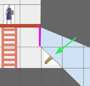
The Grid View, introduced in the last post to represent the level geometry as seen by an actor from their vantage point, can now represent views where the same underlying cell might show up multiple times due to portal connections. Furthermore, we might have weird cases where one square cell might contain slices from different areas of the map:
The green arrow points at a view cell which, due to the portal (magenta), has two sections of different grid cells.
Before, the grid view was a simple 2D array with one cell per tile. Now, that is no longer the case.
The updated grid view is organized around ViewNodes, ShadowSegments, and ViewTransforms:
struct GridView {
    // The grid tile the view is centered on
    CellIndex center;

    // The first ViewNode in each view cell.
    // 0xFFFF if there is no view node in that cell.
    u16 head_node_indices[GRID_VIEW_MAX_X][GRID_VIEW_MAX_Y];

    u16 n_nodes;
    ViewNode nodes[GRID_VIEW_MAX_NODES];

    // Shadowcast sectors.
    u16 n_shadow_segments;
    ShadowSegment shadow_segments[GRID_VIEW_MAX_NODES];

    // The transforms for the view as affected by portals.
    u8 n_view_transforms;
    ViewTransform view_transforms[GRID_VIEW_MAX_TRANSFORMS];
};
Most of the time, a given cell in the grid view will contain a single cell in the underlying grid. However, as we saw above, it might see more than one. Thus, we can look up a linked list of ViewNodes per view cell, with an intrusive index to its child (if any). Each such node knows which underlying grid cell it sees, whether it is connected in each cardinal direction to its neighbor view cells, and what sector of the view it contains:
struct ViewNode {
    CellIndex cell_index;

    // Intrusive data pointer, indexing into the GridView nodes array,
    // to the next view node at the same ViewIndex, if any.
    // 0xFFFF if there is no next view node.
    u16 next_node_index;

    // Whether this view node is continuous with the view node in the
    // given direction.
    // See direction flags.
    u8 connections;

    // The sector this view node represents.
    Sector sector;

    // The stencil id for this view node.
    // Identical to the transform_index + 1.
    u8 stencil_id;
};
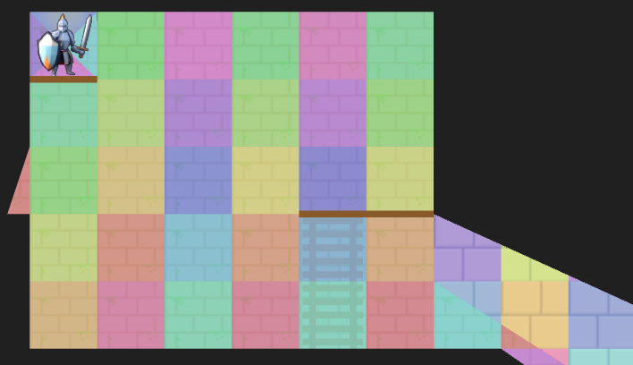
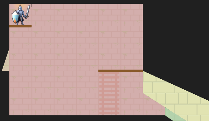
We can now represent cases like the motivating portal scenario:
I’ve given the region on the other side of the portal different tile backgrounds to make it more obvious.
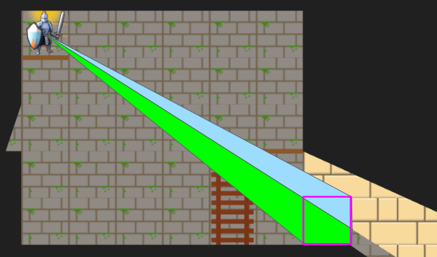
In the last post, we constructed the grid view with breadth-first search (BFS) from the center tile. Now, since we’re working with polar segments that strictly expand outwards, we can actually get away with the even simpler depth-first search (DFS). Everything is radial, and the farther out we get, the narrower our beams are:
A debug view showing the final shadow cast segments.
The search logic is a bit more complicated given that we have to narrow down the segment every time we pass through a tile’s edge, we’re saving view nodes in the new intrusive linked list structure, and edge traversals have to check for portals. Solid edges terminate and trigger the saving of a shadow segment.
Portal traversals have the added complexity of changing physically where we are in the underlying grid. If we think of the underlying grid as one big mesh, we effectively have to position the mesh differently when rendering the stuff on the other side of the portal. That information is stored in the ViewTransform, and it is also given its own stencil id.
A debug view of the view nodes. We fully see many cells, but some cells we only partially see. The origin is currently split into four views in order for view segments to never exceed 180 degrees.
Above we can see an overlay of the resulting view nodes. There is a little sliver of a cell we can see for a passage off to the left, and there are the two passages, one with a portal, that we can see on the right. The platforms (little brown rectangles) do not block line of sight.
The Stencil Buffer
Now that we have the grid view, how do we render it? It is pretty easy to render a square cell, but do we now have to calculate the part of each cell that intersects with the view segment? We very much want to avoid that!
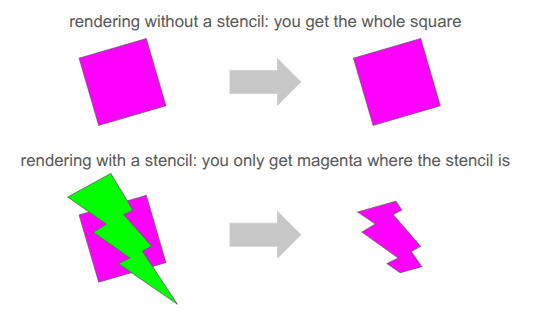
Clean rendering is accomplished via the stencil buffer, which is a feature in graphics programming that lets us mask out arbitrary parts of the screen when rendering:
We’ve already been using several buffers when rendering. We’re writing to the RGB color buffers, and 3D occlusion is handled via the depth buffer. The stencil buffer is just an additional buffer (here, one byte per pixel), that we can use to get a stenciling effect.
At one byte (8 bits) per pixel, the stencil buffer can at first glance only hold 8 overlapping stencil masks at once. However, with our 2D orthographic setup, our stencil masks never overlap. So, we can just write 255 unique values per pixel (reserving 0 for the clear).
We simply write the shadow segments to the stencil buffer, setting the buffer to the appropriate stencil ID:
The stencil buffer has four stencil masks – the red region in the main chamber, the little slice of hallway to the left, the green region through the portal leading back into the same room, and the yellow region through a different portal to an entirely different room.
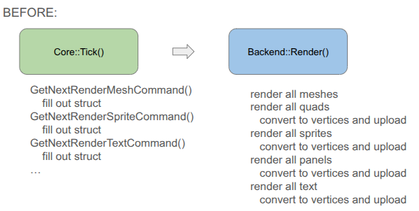
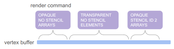
Our rendering pipeline now needs to support masking with these stencil IDs. In January we covered the render setup, which involved six different types of render commands that the game could send to the backend:
render mesh – render a 3D mesh with lighting, already uploaded to the GPU
render local mesh – render a 3D mesh without lighting, sending vertices from the CPU
render quad – an old simple command to render a quad
render sprite – self-explanatory
render spritesheet sprite – an old version of render sprite
render panel – renders a panel with 9-slice scaling by sending vertices from the CPU
render text – renders font glyphs by sending quads from the CPU
Having three versions of everything – rendering without stencils, rendering with stencils, and rendering to the stencil buffer itself, would triple the number of command types. That is too much!
Furthermore, we want to order the render commands such that opaque things are drawn front to back, and transparent things are then drawn back to front, and finally drawing UI elements in order at the end. That would require sorting across command types, which seems really messy.
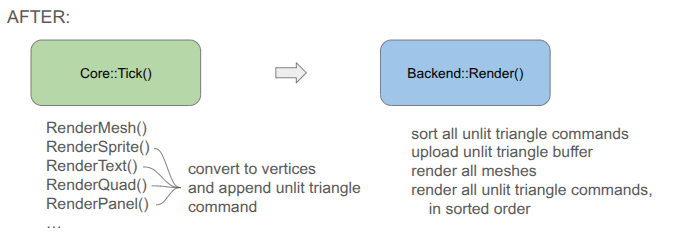
To achieve this all neatly, I collapsed everything sending vertices from the CPU to a unified command type, and have the backend fill the vertex buffer when the game creates the command:
You will notice that the game-side changed a bit. Rather than receiving a command struct and being responsible for populating all fields, I decided to move rendering to methods that expect everything you need to be passed in. This is less error prone, allows for different function signatures that populate what you need, and means I don’t actually need structs for the different command types if we’re directly converting to vertices.
Each unified command (everything but the mesh render calls) is simply:
// Determines the order in which things are rendered.
enum class PassType : u8 {
    OPAQUE = 0,
    TRANSLUCENT = 1,
    UI = 2,
};

// Determines whether and how a command uses a stencil.
enum class StencilRequirement : u8 {
    NONE  = 0, // Does not use stencils
    WRITE = 1, // Writes to the stencil buffer
    READ  = 2, // Reads from the stencil buffer
};

// Determines how the draw gets executed.
enum class DrawMode : u8 {
    ARRAYS,   // No EBO
    ELEMENTS, // With EB
};

struct RenderCommandUnlitTriangle {
    // The commands are sorted by the sort key prior to rendering, determining the order.
    // Bits 63-62 (2 bits): Pass Type (Opaque, Translucent, UI)
    // Bits 61-60 (2 bits): Stencil Requirement
    // Bits 59    (1 bit):  Draw Mode
    // Bits 58-51 (8 bits): Stencil ID (0 for none)
    // Bits 50-32  <reserved>
    // Bits 31-0  (32 bits)
    //   In Opaque:      front-to-back distance
    //   In Translucent: back-to-front distance
    //   In UI:          sequence ID
    u64 sort_key;

    // Draw Arguments
    u32 n_vertices; // Number of vertices to draw
    u32 i_vertex;   // Index of the start vertex
    u32 n_indices;  // Number of indices, if using ELEMENTS
    u32 i_index;    // Index of the start element index, if using ELEMENTS
};
Apparently, this is much closer to how modern game engines structure their render commands. There is one vertex buffer that we write into as commands are added by the game, and the command just keeps track of the appropriate range. The same is true for the index buffer, which in our case is pre-populated buffer for quad rendering (so each quad takes 4 vertices and 6 indices instead of 6 vertices):
The pass type, stencil requirement, and draw mode are then baked into a sort key that we can sort on in order to automagically get the commands in the order we want: opaque < transparent < UI, with no stencil < write to stencil < read from stencil, and then grouping by whether we use the elements (index) buffer or not. We even use the lower 32 bits for additional sorting, rendering opaque things front to back (since lighting is expensive and we can discard more pixels that way), rendering transparent things back to front (required to get correct results), and rendering UI elements in the order they are created.
Being able to call glBufferData once to send all of the vertices up once at the beginning is really nice. Before, we were writing vertices and sending just the few we needed for every command type each time.
The end result is significantly simpler backend rendering code. It can become even simpler if we eventually unify the mesh rendering with the unlit triangle rendering, but I’m holding off on that because those render commands have a bunch of uniform data and then I’m switching between shaders. I’m not currently rendering transparent meshes, and if I eventually do I’ll bite the bullet and further consolidate.
Conclusion
I am quite happy to have tackled the fundamental grid representation, which as we saw ended up affecting a lot of stuff. The new grid view now needs to be properly integrated into the movement action, and then we can actually start introducing other entities like ropes, buckets and relics. No promises on specifics! We’ll let the project dictate how it should evolve.
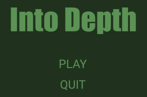
Current title screen using text rendering with the Arial TrueType fonts.
Last month we covered text rendering, which was necessary for getting the scaffolding up that supports the over-arching gameplay loop. We have a title screen, a level select screen, codex screens for seeing information about unlocked heroes and relics, and a level results screen that summarizes what was gained when completing a level. All of these are rudimentary first stabs, but ya got to make it exist first.
A lot happened in the last month, some of which I might cover in future posts. I’m not going to list everything every time, but it is interesting to see just how much stuff goes into making some sort of usable interactive experience when you’re doing a lot from scratch.
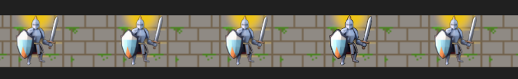
Added basic hero avatars to display when the hero is selected.
Added a tweak file system for rapidly tuning parameters.
Expanded the hero struct to include a hero level state to distinguish between in-level heroes and those that have not yet been deployed and those that have exited a level.
Added new screens.
Generalized my UI panel work to have fancier button logic that properly detects button presses, accounting for when the player clicks elsewhere but releases over the button, or presses down on the button but releases elsewhere.
Moved the game interface to simply receive one large memory buffer that the game itself then chops up into whatever smaller allocations and arenas it needs.
Introduced local mesh assets that can be directly rendered via the triangle shader from the previous post, used for basic quads and things like the selection outline.
Introduced the grid view. More on that in a bit.
Added a way to quickly identify which entities are in which cells in the stage, now more necessary due to the grid view.
Introduced schedules and simulating consequences up front rather than live.
Added the action selection panel and action sub-selection interfaces for hero deployment, move selection, and turn passing. The focus of this blog post.
Removed a bunch of earlier code pre-move selection where the active hero would move one tile or perform one action per key press.
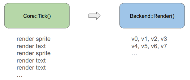
The game now looks like this:
Obviously, all art, layout, UI, etc. is an extremely early first cut and likely not the final version. We do, however, see the basic framework for a game.
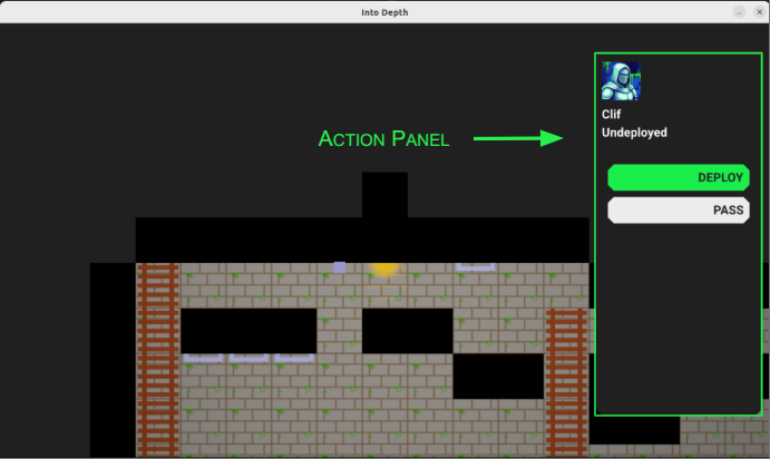
Action Panel
The main thing I want to talk about this week is the fledgling action system, starting with the action panel:
The action panel shows the active hero’s avatar, their name, their level state, and has a series of action buttons.
You’ll notice that the panel has the same color as the background. Eventually, when the field of view includes shadow casting, it should just blend with the shadows. Here is my Google slides mockup of what I’m roughly working toward:
Eventually we’ll see the whole party, along with whatever status bars we need to see, and the actions available to the hero will look fancier. Most notably, I intend to render little equilateral triangles to represent the action points available for various moves. I’m not 100% settled on how that would work, but something like that will happen.
The game loop inside a level tracks which actor is active, and then loops through four states:
Generate Actions
Select Action
Play Schedule
Done
The first state is where the game looks at the current state and generates the actions available to the actor. For heroes, these then show up as options in the action panel. The user can then select an action and get access to its dedicated UI, and use that to determine the details.
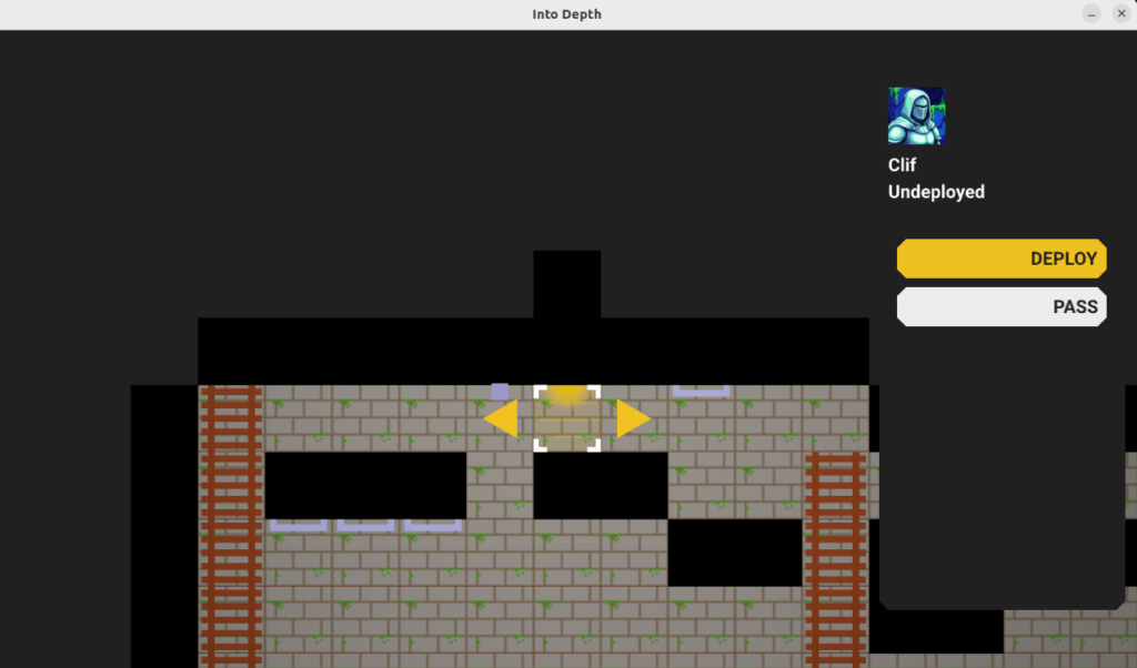
Here we’ve selected the DEPLOY action and we get a user interface for selecting which cell to deploy the hero to.
Once the user commits to an action, the action generates a schedule. This is the sequence of events that represent the outcome of the action. For example, passing the turn simply produces an event that moves the game to the next actor. Selecting a move to a cell produces a more complicated schedule that traverses multiple cells in sequence, and may involve posture changes like changing from standing to climbing.
Most importantly, a schedule contains the complete outcome of the action. Previously, if the actor planned to move, I was having the game check live, as the player moved, for triggered events like ending up over an empty shaft and then moving into a falling state. This fragments the logic and makes it harder to test planning and consequence code, as we don’t really know the consequence of an action until it is tediously simulated out over many iterations.
Instead, the schedule does all necessary consequence simulation during construction, and the game then just needs to play that out until it has completed. Given that we have the schedule, it is also quite easy to undo the entire action without having to figure out some weird reverse simulation.
This doesn’t look terribly complicated to implement, but it is actually the system that flummoxed me the most in my previous project attempt, particularly when it came to changing which actions were available based on the actor’s equipment and in enabling undo. I am much happier with how this latest rendition is set up.
The schedule is, at its core, just a DAG of events stored in a topological order:
struct Schedule {
    // Events are in a topological order
    u16 n_timeline;
    Event* timeline; // allocated on the Active linear allocator

    // The net outcome.
    u16 n_outcome;
    Event* outcomes; // allocated on the Active linear allocator

    // The opposite of the net outcome, since events are not inherently reversible.
    u16 n_undo;
    Event* undos; // allocated on the Active linear allocator
};
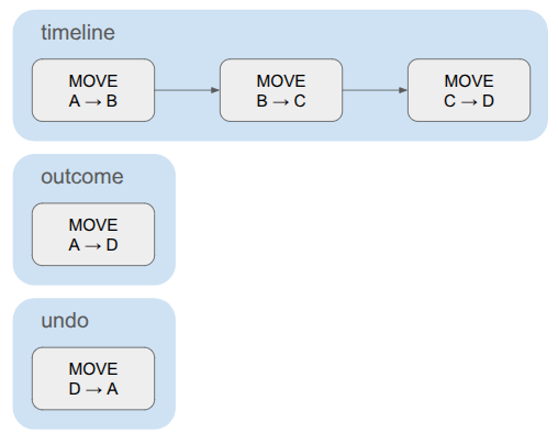
The schedule contains the full timeline, plus a compressed net outcome that only contains the events necessary to encode the overall delta. For something like a pass action, the timeline and the outcome are the same. For a move, where the actor traverses multiple cells, the timeline contains the sequence of cell traversals but the outcome only contains one cell change – from source to dest.
The schedule also contains the set of events needed to undo the action. This is very similar to the outcome, just reversed. The game events don’t all contain the information necessary to be reversed, so we construct the undo events separately.
A simple schedule for moving a hero. The timeline contains multiple cell transitions, but the outcome and undo each consist of a single event.
Events are small, composable game state deltas:
struct Event {
    u16 index;  // The event's index in the schedule. (Events are in a topological order)
    u16 beat;   // The beat that this event should be executed on. Events sharing a beat happen concurrently.
    EventType type;

    union {
        EventEndTurn end_turn;
        EventSetHeroLevelState set_hero_level_state;
        EventMove move;
        EventSetCellIndex set_cell_index;
        EventSetFacingDir set_facing_dir;
        EventSetHeroPosture set_hero_posture;
        EventAttachTo attach_to;
        EventOnBelay on_belay;
        EventOffBelay off_belay;
        EventHaulRope haul_rope;
        EventLowerRope lower_rope;
        ... etc.
    };
};
Each event knows its event type and then contains type-specific data. This is a pretty straightforward way to interleave them without annoying object-oriented inheritance code.
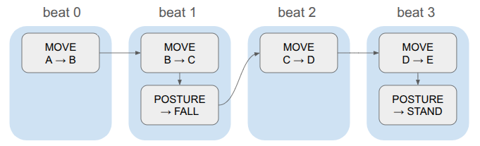
Events also contain beats. The game logic is discrete, and in order to have events run concurrently, we store them in the same beat:
Whenever we advance a beat, we apply all events in that beat and trigger any animations or whatnot and use that to determine how long to wait until we start the next beat. This keeps the event system clean (it doesn’t need to know how long a given animation will take, or even what animation is associated with an event), and gives us one centralized place for triggering animations and sounds.
When the schedule is fully played out, the game enters the done state and checks to see if the level is done. If not, it goes back to action generation.
The state for active levels thus includes the core game state (the stage), which actor’s turn it is, the active schedule (if any), the schedule playback state (event index, time in beat), and data for all of this turn’s actions:
struct ScreenState_Active {
    // The active playable area and the entities in it.
    Stage stage;

    // Stores data for the active actor's turn.
    Turn turn;

    // Stores the events that are scheduled to run.
    Schedule schedule;

    // The playback state of the schedule.
    PlaybackState playback_state;

    // The index of the active actor.
    int i_actor = 0;
    int i_actor_next;

    // Where we allocate the action data.
    // This allocator is only reset when actions are regenerated.
    LinearAllocator action_allocator;
};
Pretty clean when it comes down to it.
The Turn contains the actions generated for the current actor. Each action has a name, which then makes it easy to render the buttons for the actions in the action panel.
Actions
An action is a discrete state change available to an actor, such as passing the turn, moving through the environment, or attacking another actor. The available actions depend on the game state — an actor that is not yet deployed has a deploy action but no move action, and an actor with a bow should get an attack action with a ranged UI whereas an actor with a sword can only select the tiles within melee range.
To handle these things flexibly, actions have methods that can be specialized on a per-action basis. In modern C++, one would probably use objects and inheritance to implement a bunch of action subclasses. I am avoiding classes and am not using inheritance at allWhy? To see if I can, mostly. Folks like Casey Muratori hate on OOP a lot and I want to see what the fuss is., so instead we have a basic struct with some function pointers:
// A function pointer called to run the action UI for the action,
// once the action has been selected in the menu.
typedef void (*FuncRunActionUI)(GameState* game, RenderCommandBuffer* command_buffer, void* data, const AppState& app_state);

// A function pointer for a method that determines whether the action was committed.
typedef bool (*FuncIsActionCommitted)(const void* data);

// A function pointer for a method that builds a schedule from the action.
typedef bool (*FuncBuildSchedule)(GameState* game, void* data);

struct Action {
    char name[16]; // null-terminated

    // The key to press to perform this action
    char shortkey;

    // Data associated with the action, specialized per action type
    void* data;

    // Function pointers
    FuncRunActionUI run_action_ui;
    FuncIsActionCommitted is_action_committed;
    FuncBuildSchedule build_schedule;
};
We use the action name when displaying its button in the action panel, and its shortkey is available if the user doesn’t want to have to click the button with the mouse.
Each action also has a void* data member, which can be populated when the action is created and then used in the member functions. We’ll see an example of that shortly.
Generating the available actions is conceptually straightforward; just run a method for every action in the game that checks if that action is available, and if it is, allocates it, constructs it, and adds it to the action list:
This may seem too simple, but I think it is actually quite an advantage. I had previously been considering having various pieces of equipment be responsible for determining which actions they are associated with, and then having a way to store that metadata on the equipment, save it to disk, etc. Messy! Instead, I can just run all of these methods, every time, and if any require specific equipment, they can check for it and just quickly return false if it isn’t there.
Every action currently requires at least four methods: action generation, running the action-specific UI, a simple method that determines whether the user committed to the action, and a schedule generation. For the simple pass action, this doesn’t even need the void* data member:
// ------------------------------------------------------------------------------------------------
bool MaybeGenerateAction_Pass(Action* action, GameState* game, const Hero& hero) {

    strncpy(action->name, "PASS", sizeof(action->name));
    action->shortkey = 'p';
    action->run_action_ui = RunActionUI_Pass;
    action->is_action_committed = IsActionCommitted_Pass;
    action->build_schedule = BuildSchedule_Pass;

    return true;
}

// ------------------------------------------------------------------------------------------------
void RunActionUI_Pass(GameState* game, RenderCommandBuffer* command_buffer, void* data, const AppState& app_state) {
    // Nothing to do here.
}

// ------------------------------------------------------------------------------------------------
bool IsActionCommitted_Pass(const void* data) {
    return true;
}

// ------------------------------------------------------------------------------------------------
bool BuildSchedule_Pass(GameState* game, void* data) {
    ScreenState_Active& active = game->screen_state_active;

    // Build the schedule, which consists just of an end turn action.
    Schedule* schedule = &(game->screen_state_active.schedule);

    schedule->n_timeline = 1;
    schedule->timeline = (Event*)Allocate(&(active.action_allocator), sizeof(Event));
    ASSERT(schedule->timeline != nullptr, "BuildSchedule_Pass: Failed to allocate timeline!");

    CreateEventEndTurn(schedule->timeline, /*index=*/0, /*beat=*/0);

    // The outcome is the same.
    schedule->n_outcome = 1;
    schedule->outcomes = schedule->timeline;

    // The undo action: TODO

    return true;
}
The deploy action is more involved, and it does allocate a custom data struct:
struct DeployActionData {
    // List of legal entry cells for the hero.
    u16 n_entries;
    CellIndex entries[STAGE_MAX_NUM_ENTRIES];

    // The index of the entry we are looking at.
    int targeted_entry;

    // Whether the entry has been selected.
    bool entry_selected;
};

// ------------------------------------------------------------------------------------------------
void InitActionData_Deploy(DeployActionData* data) {
    data->n_entries = 0;
    data->targeted_entry = 0;
    data->entry_selected = false;
}

// ------------------------------------------------------------------------------------------------
bool MaybeGenerateAction_Deploy(Action* action, GameState* game, const Hero& hero) {

    if (hero.level_state != HERO_LEVEL_STATE_UNDEPLOYED) {
        // Hero does not need to be deployed
        return false;
    }

    ScreenState_Active& active = game->screen_state_active;
    const Stage& stage = active.stage;

    // Allocate the data for the action
    action->data = Allocate(&(active.action_allocator), sizeof(DeployActionData));
    DeployActionData* data = (DeployActionData*)action->data;
    InitActionData_Deploy(data);

    // Run through all stage entries and find the valid places to deploy
    for (u16 i_entry = 0; i_entry < stage.n_entries; i_entry++) {
        CellIndex cell_index = stage.entries[i_entry];

        ASSERT(!IsSolid(stage, cell_index), "Entry cell is solid!");

        // Ensure that the cell is not occupied by another hero
        if (IsHeroInCell(stage, cell_index)) {
            continue;
        }

        // Add the entry.
        data->entries[data->n_entries++] = cell_index;
    }

    if (data->n_entries == 0) {
        // No valid entries
        return false;
    }


    strncpy(action->name, "DEPLOY", sizeof(action->name));
    action->shortkey = 'd';
    // action.sprite_handle_icon = // TODO
    action->run_action_ui = RunActionUI_Deploy;
    action->is_action_committed = IsActionCommitted_Deploy;
    action->build_schedule = BuildSchedule_Deploy;

    return true;
}

// ------------------------------------------------------------------------------------------------
void RunActionUI_Deploy(GameState* game, RenderCommandBuffer* command_buffer, void* data, const AppState& app_state) {

    DeployActionData* action_data = (DeployActionData*)data;

    const TweakStore* tweak_store = &game->tweak_store;
    const f32 kSelectItemFlashMult = TWEAK(tweak_store, "select_item_flash_mult", 2.0f);
    const f32 kSelectItemReticuleAmplitude = TWEAK(tweak_store, "select_item_reticule_amplitude", 0.25f);
    const f32 kSelectItemFlashAlphaLo = TWEAK(tweak_store, "select_item_flash_alpha_lo", 0.1f);
    const f32 kSelectItemFlashAlphaHi = TWEAK(tweak_store, "select_item_flash_alpha_hi", 0.9f);
    const f32 kSelectItemArrowOffsetHorz = TWEAK(tweak_store, "select_item_arrow_offset_horz", 1.0f);
    const f32 kSelectItemArrowScaleLo = TWEAK(tweak_store, "select_item_arrow_scale_lo", 1.0f);
    const f32 kSelectItemArrowScaleHi = TWEAK(tweak_store, "select_item_arrow_scale_hi", 1.0f);

    // TODO: This is probably lagged by one frame.
    const glm::mat4 clip_to_world = CalcClipToWorld(command_buffer->render_setup.projection, command_buffer->render_setup.view);
    const glm::vec2 mouse_world = CalcMouseWorldPos(app_state.pos_mouse, 0.0f, clip_to_world, app_state.window_size);

    bool deploy_hero_to_target_cell = false;

    // Set the hero's location to one tile over the entry we are looking at.
    // This is a hacky way to handle the fact that the hero is not in the level yet

    // and that the camera is centered on the hero
    ScreenState_Active& active = game->screen_state_active;
    Hero* hero = active.stage.pool_hero.GetMutableAtIndex(active.i_actor);
    const CellIndex cell_index = action_data->entries[action_data->targeted_entry];
    MoveHeroToCell(&active.stage, hero, {cell_index.x, (u16)(cell_index.y + 1)});
    hero->offset = {0.0f, 0.0f};

    // Render the entrance we are currently looking at.
    {
        const f32 unitsine = UnitSine(kSelectItemFlashMult * game->t);

        RenderCommandLocalMesh& local_mesh = *GetNextLocalMeshRenderCommand(command_buffer);
        local_mesh.local_mesh_handle = game->local_mesh_id_quad;
        local_mesh.screenspace = false;
        local_mesh.model = glm::translate(glm::mat4(1.0f), glm::vec3(0.0f, -1.0f, RENDER_Z_FOREGROUND));
        local_mesh.color = kColorGold;
        local_mesh.color.a = Lerp(kSelectItemFlashAlphaLo, kSelectItemFlashAlphaHi, unitsine);

        {
            RenderCommandLocalMesh& reticule = *GetNextLocalMeshRenderCommand(command_buffer);
            reticule.local_mesh_handle = game->local_mesh_id_corner_brackets;
            reticule.screenspace = false;
            reticule.model = glm::translate(glm::mat4(1.0f), glm::vec3(0.0f, -1.0f, RENDER_Z_FOREGROUND + 0.1f));
            reticule.model = glm::scale(reticule.model, glm::vec3(unitsine * kSelectItemReticuleAmplitude + 1.0f));
            reticule.color = kColorWhite;
        }

        // Run button logic on the targeted entry.
        const Rect panel_ui_area = {
                .lo = glm::vec2(- 0.5f, - 1.5f),
                .hi = glm::vec2(+ 0.5f, - 0.5f)};
        const UiButtonState button_state = UiRunButton(&game->ui, panel_ui_area, mouse_world);

        if (button_state != UiButtonState::NORMAL) {
            local_mesh.color.x = Lerp(local_mesh.color.x, kColorWhite.x, unitsine);
            local_mesh.color.y = Lerp(local_mesh.color.y, kColorWhite.y, unitsine);
            local_mesh.color.z = Lerp(local_mesh.color.z, kColorWhite.z, unitsine);
        }

        if (button_state == UiButtonState::TRIGGERED) {
            deploy_hero_to_target_cell = true;
        }
    }

    bool pressed_left = IsNewlyPressed(app_state.keyboard, 'a');
    bool pressed_right = IsNewlyPressed(app_state.keyboard, 'd');

    // Render two arrow-like triangles that let us switch between options.
    {
        const f32 unitsine = UnitSine(game->t);
        const f32 scale = Lerp(kSelectItemArrowScaleLo, kSelectItemArrowScaleHi, unitsine);

        const glm::vec2 halfdims = glm::vec2(0.433f * scale, 0.5f * scale); // NOTE: Rotated

        { // Left triangle
            const glm::vec2 pos = glm::vec2(-kSelectItemArrowOffsetHorz, -1.0f);

            const Rect panel_ui_area = {
                    .lo = pos - halfdims,
                    .hi = pos + halfdims};
            const UiButtonState button_state = UiRunButton(&game->ui, panel_ui_area, mouse_world);

            RenderCommandLocalMesh& local_mesh = *GetNextLocalMeshRenderCommand(command_buffer);
            local_mesh.local_mesh_handle = game->local_mesh_id_triangle;
            local_mesh.screenspace = false;
            local_mesh.model =
            glm::scale(
                glm::rotate(
                    glm::translate(glm::mat4(1.0f), glm::vec3(pos.x, pos.y, RENDER_Z_FOREGROUND)),
                    glm::radians(90.0f),
                    glm::vec3(0.0f, 0.0f, 1.0f)
                ),
                glm::vec3(scale, scale, 1.0f)
            );
            local_mesh.color = kColorGold;

            if (button_state != UiButtonState::NORMAL) {
                local_mesh.color = glm::mix(local_mesh.color, kColorWhite, unitsine);
            }

            // Check for pressing the button.
            if (button_state == UiButtonState::TRIGGERED) {
                pressed_left = true;
            }
        }
        { // Right triangle
            const glm::vec2 pos = glm::vec2(kSelectItemArrowOffsetHorz, -1.0f);

            const Rect panel_ui_area = {
                    .lo = pos - halfdims,
                    .hi = pos + halfdims};
            const UiButtonState button_state = UiRunButton(&game->ui, panel_ui_area, mouse_world);

            RenderCommandLocalMesh& local_mesh = *GetNextLocalMeshRenderCommand(command_buffer);
            local_mesh.local_mesh_handle = game->local_mesh_id_triangle;
            local_mesh.screenspace = false;
            local_mesh.model =
            glm::scale(
                glm::rotate(
                    glm::translate(glm::mat4(1.0f), glm::vec3(pos.x, pos.y, RENDER_Z_FOREGROUND)),
                    glm::radians(-90.0f),
                    glm::vec3(0.0f, 0.0f, 1.0f)
                ),
                glm::vec3(scale, scale, 1.0f)
            );
            local_mesh.color = kColorGold;

            if (button_state != UiButtonState::NORMAL) {
                local_mesh.color = glm::mix(local_mesh.color, kColorWhite, unitsine);
            }

            // Check for pressing the button.
            if (button_state == UiButtonState::TRIGGERED) {
                pressed_right = true;
            }
        }
    }


    // Process the presses, which can come from keys or clicking the arrows.
    if (pressed_left) {
        CircularDecrement(action_data->targeted_entry, (int)action_data->n_entries);
    } else if (pressed_right) {
        CircularIncrement(action_data->targeted_entry, (int)action_data->n_entries);
    }

    if (deploy_hero_to_target_cell) {
        action_data->entry_selected = true;
    }
}

// ------------------------------------------------------------------------------------------------
bool IsActionCommitted_Deploy(const void* data) {
    const DeployActionData* action_data = (DeployActionData*)data;
    return action_data->entry_selected;
}

// ------------------------------------------------------------------------------------------------
bool BuildSchedule_Deploy(GameState* game, void* data) {
    ScreenState_Active& active = game->screen_state_active;

    const Hero* hero = active.stage.pool_hero.GetAtIndex(active.i_actor);
    const CellIndex src = hero->cell_index;
    const CellIndex dst = {src.x, (u16)(src.y - 1)};

    // Build the schedule, which changes the hero's level state and moves them to the entry (1 cell down).
    Schedule* schedule = &(game->screen_state_active.schedule);

    {
        schedule->n_timeline = 2;
        schedule->timeline = (Event*)Allocate(&(active.action_allocator), schedule->n_timeline * sizeof(Event));
        ASSERT(schedule->timeline != nullptr, "BuildSchedule_Deploy: Failed to allocate timeline!");

        CreateEventSetHeroLevelState(schedule->timeline, /*index=*/0, /*beat=*/0, hero->id, HERO_LEVEL_STATE_IN_LEVEL);
        CreateEventMove(schedule->timeline + 1, /*index=*/1, /*beat=*/0, hero->id, Direction::DOWN, src, dst);
    }

    // The outcome is the same.
    schedule->n_outcome = 1;
    schedule->outcomes = schedule->timeline;

    // Undo: TODO

    return true;
}
Move Actions
The move action is significantly more complicated than the deploy or pass actions.
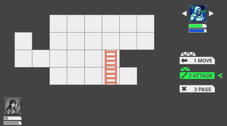
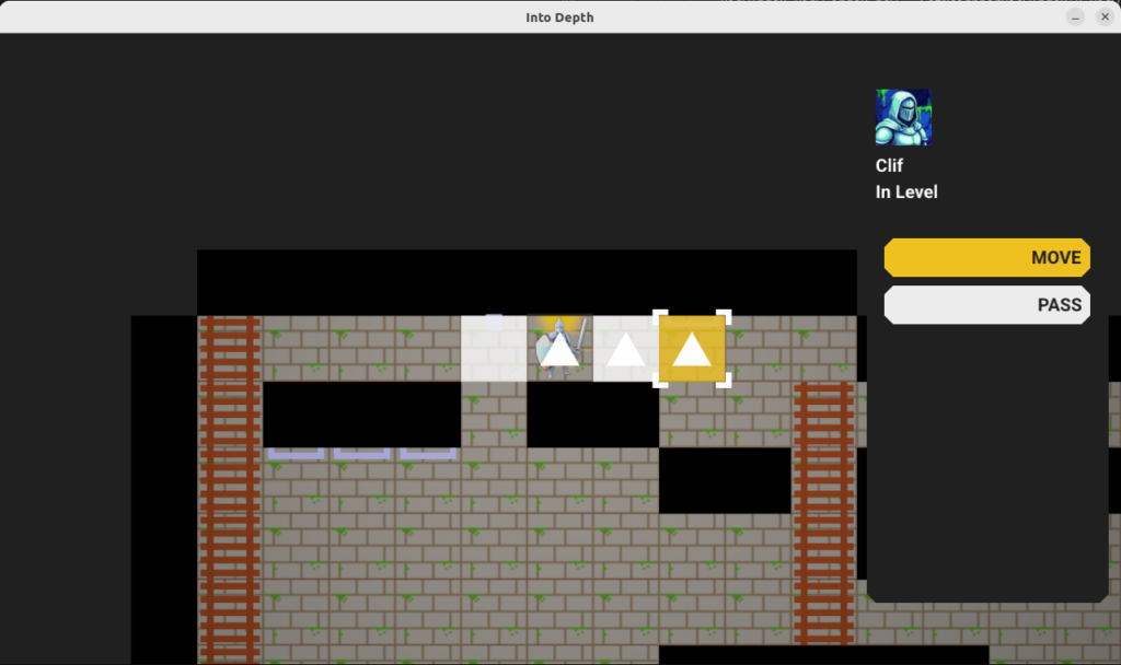
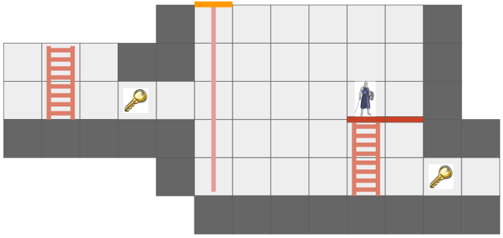
The move action highlights all valid target cells, allowing the player to select one to move to. Once selected, the shortest path to that cell is taken by the hero, and all consequences are simulated (e.g. falling, triggering a trap) and built into a schedule.
The move action UI, which here has three valid target cells (since falling ends the search). The tile under the mouse cursor is highlighted in yellow, has square angle brackets, and the shortest path is shown as a trail of equilateral triangles.
In order to support these features, the move action logic needs to know what the reachable cells are and what the shortest paths to them are. This is achieved by running Dijkstra’s algorithm from the actor’s initial state. The state space is not merely cell positions, but also includes the actor’s facing direction and their posture (standing, on ladder, etc.).
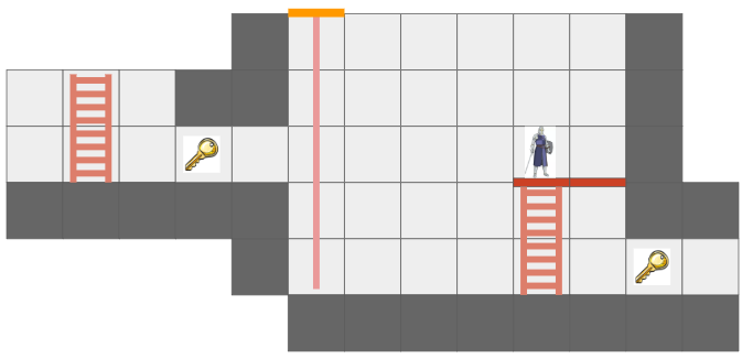
There is one additional point of complication, and that is that we want this game to only reason about cells that are visible from the hero’s current vantage point, and we eventually want to support non-Euclidean connections like portals:
In this mockup, the key is visible twice because the hallway has a portal loop-back connection.
In order to achieve this, we introduce a new representation of the level geometry visible to an actor, the GridView:
struct GridView {
    // The grid tile the view is centered on
    CellIndex center;

    CellIndex cell_indices[GRID_VIEW_MAX_X][GRID_VIEW_MAX_Y];
    u8 flags[GRID_VIEW_MAX_X][GRID_VIEW_MAX_Y];
};
This view has a finite size, much smaller than the overall level grid, that is big enough to fit the screen. The view is always centered on an actor, and the cells in the view are then indices into the cells in the underlying level grid. If a level grid cell is connected by a non-Euclidean portal to another cell, the view can just index into the correct cells on either side of the portal. Constructing the grid view is a straightforward breadth-first search from the center tile.
Note: I am actually temporarily making this simpler than it really is. To do this properly, we’ll need a fancier data structure that is not a grid but can handle sectors, because one view cell may actually contain view sectors of multiple level cells:
This view cell is visible twice, once with a cell containing a key, with this portal (magenta) set up.
We thus run Dijkstra’s algorithm in this grid view, starting from the center cell where the actor is. The same cell may be visible multiple times in the grid view, and we will correctly be able to route to that cell via multiple paths.
The search assigns a cost for each state change, and only searches up to a maximum cost. Very soon, actors will have action points to spend per turn, and it won’t be possible to move further than are affordable given the action points currently available.
The move action custom data struct is:
struct MoveActionData {
    // We can only ever move to a visible tile, so for now, we can
    // just allocate a grid's worth of potential targets.

    // The cheapest cost to reach each move state.
    u16 costs[GRID_VIEW_MAX_X][GRID_VIEW_MAX_Y][/*num directions=*/2][kNumHeroPostures];

    // The parent state on the shortest path that arrives at the given state.
    // I.E., if [1][2][LEFT][STANDING] contains {2,2,LEFT,STANDING}, then we took a step over.
    // The root state points to itself.
    MoveState parents[GRID_VIEW_MAX_X][GRID_VIEW_MAX_Y][/*num directions=*/2][kNumHeroPostures];

    // Used to track whether a view cell has been visited.
    u32 visit_frame;
    u32 visits[GRID_VIEW_MAX_X][GRID_VIEW_MAX_Y];

    ViewIndex view_index_target;  // Target view cell index for the move.
    bool entry_selected;
};
Having completed the search, we are able to render all reachable tiles, render a reticle over the cell the user’s mouse is over, and if the cell is reachable, we can backtrack over the cell’s parents to render the cells traversed to get there. (Since states include more than just cell changes, and we don’t want to render multiple times to the same cell, we also store a u32 visit frame that we can use to mark cells we have rendered to in order to avoid rendering to the same cell multiple times.)
Finally, when the user clicks on a cell to commit the action, we compute the schedule by:
Extracting the shortest path by traversing back to the source node.
Writing the shortest path out one state change at a time.
Simulating consequences (like falling) after every step, and if any consequences do take place, ending the planned schedule there and appending all consequence events.
This process makes a copy of the current state and applies all changes there. Making a copy, while taking memory, has the advantage of not polluting the actual game state and giving us a second Stage to compare the current Stage to in order to get the overall schedule delta.
Conclusion
With the action system in place, the foundation is laid for actual gameplay. Next time, we’ll look at introducing some core entities back in (ropes, buckets, relics) and managing the overall gameplay cycle.
Into Depth is the name of a little game project I have been working on for over a year now. Its roots go back even further, to the 2D platformer I had started working on two years ago. The platformer ended up teaching me a lot about OpenGL, which I have continued to use in a fairly low-level manner in this new project.
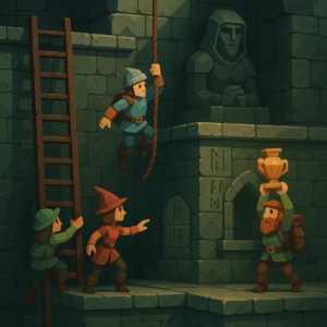
Concept image by ChatGPT.
In a nutshell, the game is a simplification of the 2D platformer born both from managing complexity and wanting something I could reasonably make multiplayer and play with my friends online. Into Depth is a turn-based 2D sidescroller on a grid. Kind of like Gloomhaven, but vertical:
An early mockup from my Google slides design doc.
The team of heroes descends into dungeons (e.g., down the rope in the image above) with the goal of retrieving relics. Oftentimes these relics are heavy and require hauling to get them back to the surface. Collected relics can be equipped and used in other levels, and teams may revisit levels in order to get even deeper. That’s the rough idea.
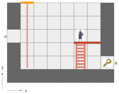
There are additional details, of course. For example, I want non-Euclidean geometry to play a role. In the screen above, the two edges labeled ‘a’ are joined, such that the hero’s view is:
The hero can see the key from two different vantage directions because of the portal.
This is made more interesting by having each hero only be able to see what is in their line of sight. Not only does that add an element of discovery and the need to juggle teammates’ perspectives, it also enables stealth mechanics.
Solid geometry blocks the view of what is behind it. This image was from before I went orthographic.
I am writing this myself, for fun, in my spare time. My primary goal is to learn how things work, and to actually get something playable for myself and my friends.
Why these restrictions? Because I am a big fan of Casey Muratori, Jonathan Blow, and the do-it-yourself attitude of understanding your code. It is a great way to learn how it all works, and it is fun! Presumably it leads to smaller executables and faster code too.
The art you see here is programmer art, since I am a programmer. That is good enough for now. My long-term vision is to have a low-poly aesthetic and mostly not use sprites, since I should be able to author low-poly meshes myself. The scene will be 3D with effects like lighting, but will be rendered in orthographic since that just makes it so much easier to see and work with the grid.
Font Glyphs + Sprites
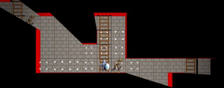
I was most recently working on some basic shaders for the game. I had just added font rendering with its own shader for rendering glyph quads. A UI system typically needs things beyond just font glyphs, like UI panels and sprite icons, and those are mostly just basic quads as well. It seemed obvious that I could share a shader for the dual uses of rendering font quads and rendering sprite quads:
The shader is really simple. In the vertex shader, the position is just:
gl_Position = proj_view * vec4(aPosWorld, 1.0);
And then the fragment shader uses the input color as a componentwise multiplier after looking up the texture value via the UV coordinate:
vec4 tex_color = texture(u_texture, uv);
FragColor = color * texture_rgba;
The font atlas has white glyphs, which means this color multiplier produces fonts that look like we want. Colored sprites are typically rendered with color = [1,1,1,1] so that we don’t affect them, but you can also tint them by changing up the values.
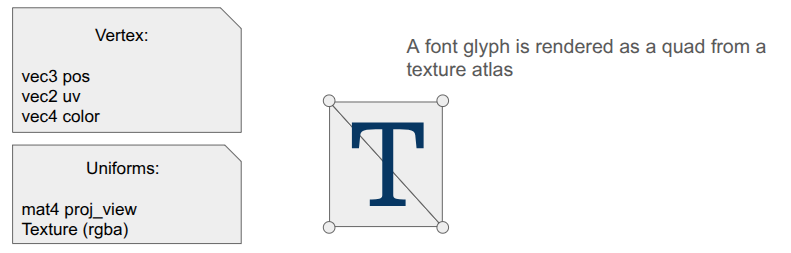
Rendering quads is also straightforward, but when you’re doing it all yourself, there is still a fair amount of stuff to keep track of. Every glyph in the font has a packed quad that tells us its size and its UV coordinates in the font atlas. We write the quad vertices into a VBO, and rather than writing six vertices to get the two triangles per quad, we only write the four unique ones and use an EBO to define the quads by indexing into the vertex array (as is standard practice):
Each frame, the backend fills up a vertex buffer and sends it to the VBO for rendering. This only needs to happen once, if the sprites and the font glyphs are all packed into the same texture and everything uses the same projection and view matrix.
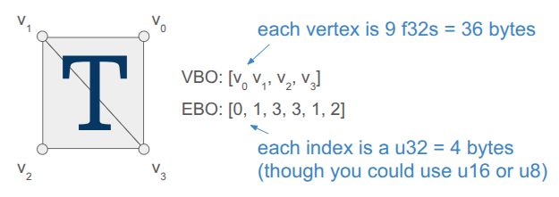
Render Commands
The core game code does not directly fill the vertex buffer. Instead the core game code issues more simple render commands. These commands are simple, higher-level descriptions of what we want rendered, making the core game code fast and separating out the task of deciding how to render everything up to the backend.
For example, a render text command is:
struct RenderCommandTextLine {
    FontHandle font_handle;
    glm::vec2 pos;       // Bottom-left of the first glyph
    f32 letter_size;     // Multiplier off of default
    f32 letter_spacing;  // Multiplier off of default
    s8 text;             // Must last until rendered
    glm::vec4 color;     // RGBA componentwise color multipliers
};
It is up to the backend to convert that higher-level specification into the actual quad vertices, moving that non-trivial logic out of the core game loop and into its own location. The render command thus acts as an API between the game and the backend. Any new backend that we support in the future must be able to render these things.
In the future, when I might have partially transparent objects, the backend can do more sophisticated things like render all opaque geometry first and then sort the transparent objects by depth and render them in a second pass. Something like that is very hard to do when the core logic is rendering as it goes.
Including Triangles
So far, we have a shader that can render both font glyphs and sprites. That’s nice, but I want Into Depth to have a low-poly, flat-color aesthetic. I wanted to add UI panels that underlay the text, and I want those to be tessellated:
A panel like that is comprised of a relatively small number of triangles when compared to a modern 3D character mesh (~40 vs. 1000’s). It should be cheap enough for us to directly write that geometry out every frame.
Our font + sprite shader can actually be used to draw basic triangles, we just need to point all three vertices of the triangle to all-white uv coordinates so that we get the color we want. This is achieved by including a \(1 \times 1\) white spriteThis technique was mentioned in the Wookash Podcast with Omar Cornut of Dear ImGui..
I thus define some additional render commands, such as RenderCommandPanel, that act as high-level descriptions of what should be rendered, and then have the backend construct the mesh live in the vertex buffer and send it over. Doing this does not use the quad-specific EBO, so for now I’m just using a glDrawArrays call instead of a glDrawElements call.
I did make one adjustment to the shader – rather than switching out the textures depending on my use, I just have an array of textures that I can leave bound and have each vertex declare which one its UV coordinate applies to:
I pack my fonts into a font atlas that is uploaded as the first texture, then have a series of sprite atlases.
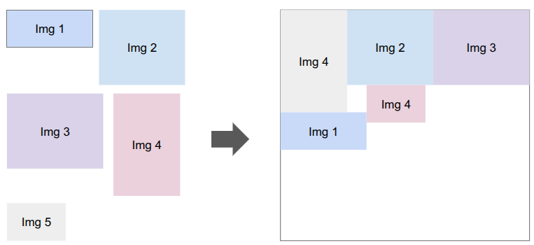
Sprite Packing
I need to bake my font glyphs and my sprites into a series of textures that my shader can then use. There are plenty of tools that do sprite packing for you. I was already using stb_truetype and stb_rect_pack to create my font atlas, so I decided to write my own sprite packer on top of stb_rect_pack.
Conceptually, it is really simple. I give it a set of individual sprites, and it keeps trying to pack as many as possible into a new texture until everything is packed. The only little gotcha is that a \(w \times h\) sprite is packed as a \(w+2 \times h+2\) rectangle in order for it to be padded with a 1-pixel extended border to fight edge bleeding caused by inaccuracies in UV coordinates between mipmap levels.
Shader Code Organization
Beyond assets, shaders themselves tend to more complexity than you’d think because the code to use them ends up spread all over the codebase. The vertex and fragment shader definitions are often two separate .glsl files, which live in their own folder alongside the other shaders. The C++ side typically needs a vertex struct defined somewhere, and then we need both CPU-side vertex buffers and references to the GPU-side shader program IDs, VAO, VBO, and EBOs. Whenever we use a shader, we need to activate it, which involves more code that has to use these references and set various shader uniforms.
I’ve adopted a few enhancements to reduce the degree of code spread.
The first thing I did was unify the vertex and fragment shaders into a single .glsl file. Since we just read in the file and upload it to the GPU before calling glCompileShader, we can actually process out the necessary portions ourselves. Writing both shaders in the same file helps keep their interdependencies consistent.
#version 330 core
#ifdef VERTEX_SHADER
layout (location = 0) in vec3 aPosWorld; layout (location = 1) in vec4 aVertexColor; // rgba layout (location = 2) in vec2 aTexCoords;
This was nice, but I actually ended up further simplifying by having a single .h file that defines the shader data relevant to the CPU side. The vertex and fragment shaders are still defined in one place, but as explicit strings, and we additionally define a vertex layout:
#pragma once
#include "util/strings.h"
#include "util/vertex_layout.h"
constexpr int kNumUnlitTriangleShaderTextures = 8;
// The vertex data structure (CPU-side)
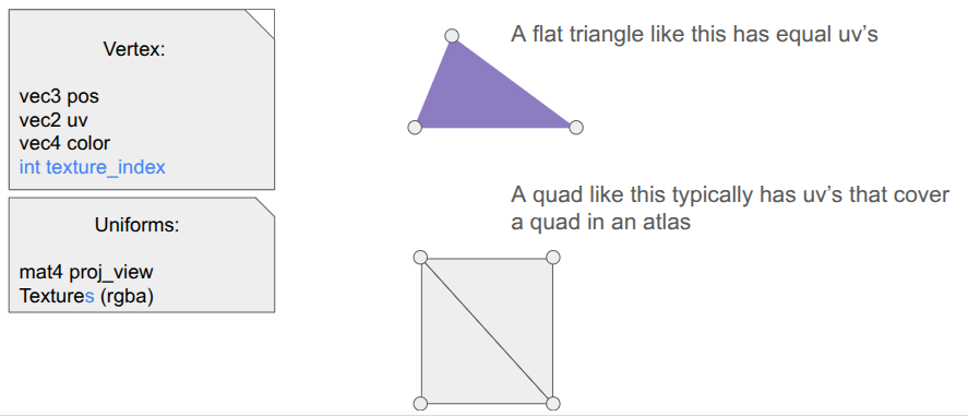
struct UnlitTriangleVertex {
glm::vec3 pos;
glm::vec4 rgba;
glm::vec2 uv;
int texture_index;
};
// The shader definition
struct UnlitTriangleShaderDefinition {
static constexpr const char* kName = "UnlitTriangle";
static constexpr VertexElement kVertexElements[4] = {
{ShaderDataType::Vec3F, "aPosWorld", false, offsetof(UnlitTriangleVertex, pos )},
{ShaderDataType::Vec4F, "aRGBA", false, offsetof(UnlitTriangleVertex, rgba )},
{ShaderDataType::Vec2F, "aUV", false, offsetof(UnlitTriangleVertex, uv )},
{ShaderDataType::I32, "aTexIndex", false, offsetof(UnlitTriangleVertex, texture_index)},
};
static constexpr VertexLayout kVertexLayout = {
kVertexElements,
sizeof(kVertexElements) / sizeof(kVertexElements[0]),
sizeof(UnlitTriangleVertex)
};
static constexpr const char* kVertexShaderSource = R"(
#version 330 core
layout (location = 0) in vec3 aPosWorld;
layout (location = 1) in vec4 aRGBA;
layout (location = 2) in vec2 aUV;
layout (location = 3) in int aTexIndex;
out vec4 rgba;
out vec2 uv;
flat out int texture_index; // 'flat' means do not interpolate
uniform mat4 proj_view; // proj * view
void main()
{
gl_Position = proj_view * vec4(aPosWorld, 1.0);
rgba = aRGBA;
uv = aUV;
texture_index = aTexIndex;
}
)";
static constexpr const char* kFragmentShaderSource = R"(
#version 330 core
in vec4 rgba;
in vec2 uv;
flat in int texture_index;
out vec4 FragColor;
uniform sampler2D textures[8];
void main()
{
vec4 texture_rgba;
// The 'switch trick' is faster/safer on some drivers.
switch(texture_index) {
case 0: texture_rgba = texture(textures[0], uv); break;
case 1: texture_rgba = texture(textures[1], uv); break;
case 2: texture_rgba = texture(textures[2], uv); break;
case 3: texture_rgba = texture(textures[3], uv); break;
case 4: texture_rgba = texture(textures[4], uv); break;
case 5: texture_rgba = texture(textures[5], uv); break;
case 6: texture_rgba = texture(textures[6], uv); break;
case 7: texture_rgba = texture(textures[7], uv); break;
default: texture_rgba = vec4(1.0,0.0,1.0,1.0); break; // magenta
}
FragColor = rgba * texture_rgba;
}
)";
};
The vertex layout is just a programmatic representation of the inputs to the Vertex shader. This avoids having to have VBO-creation code that lives elsewhere depend on this shader. We can go from code like this:
My OpenGL backend has the general SetUpVertexAttrib, but it doesn’t have to change if we change the shader. The backend additionally has structs for the GPU object references, the shader uniforms, and their locations:
struct UnlitTriangleShaderRefs {
    GLuint shader_program_id;

    GLuint vao; // vertex array object
    GLuint vbo; // vertex buffer object
    size_t vbo_tri_capacity;  // Number of triangles we have space for in the VBO.

    GLuint ebo_quads; // prepopulated with quad indices
};

struct UnlitTriangleShaderUniforms {
    GLint uniformloc_proj_view; // proj * view from glGetUniformLocation
    GLint uniformloc_textures;

    GLuint texture_ids[kNumUnlitTriangleShaderTextures];
};
This organization scheme has, so far, been much nicer to work with.
Conclusion
When you are writing everything yourself, there is a lot to keep track of. Most of my previous attempts at coding a game “from scratch” struggled under mounting complexity. Unifying font, sprite, and basic unlit geometry rendering under one shader helps alleviate that complexity. Even more so, having good separations of concern between the core game logic and the backend lets the game logic just have simple references to assets and focus on the game, and the backend figure out how to fill vertex buffers and ship them to the GPU.