Into Depth is the name of a little game project I have been working on for over a year now. Its roots go back even further, to the 2D platformer I had started working on two years ago. The platformer ended up teaching me a lot about OpenGL, which I have continued to use in a fairly low-level manner in this new project.
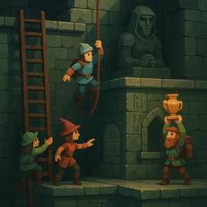
Concept image by ChatGPT.
In a nutshell, the game is a simplification of the 2D platformer born both from managing complexity and wanting something I could reasonably make multiplayer and play with my friends online. Into Depth is a turn-based 2D sidescroller on a grid. Kind of like Gloomhaven, but vertical:
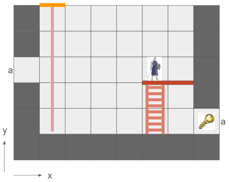
An early mockup from my Google slides design doc.
The team of heroes descends into dungeons (e.g., down the rope in the image above) with the goal of retrieving relics. Oftentimes these relics are heavy and require hauling to get them back to the surface. Collected relics can be equipped and used in other levels, and teams may revisit levels in order to get even deeper. That’s the rough idea.
There are additional details, of course. For example, I want non-Euclidean geometry to play a role. In the screen above, the two edges labeled ‘a’ are joined, such that the hero’s view is:
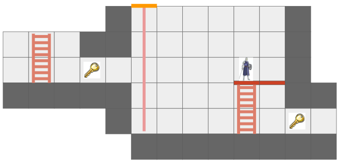
The hero can see the key from two different vantage directions because of the portal.
This is made more interesting by having each hero only be able to see what is in their line of sight. Not only does that add an element of discovery and the need to juggle teammates’ perspectives, it also enables stealth mechanics.
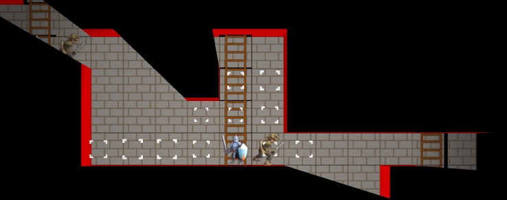
Solid geometry blocks the view of what is behind it. This image was from before I went orthographic.
I am writing this myself, for fun, in my spare time. My primary goal is to learn how things work, and to actually get something playable for myself and my friends.
I am using C++ and VS Code, on Linux. I try to minimize library use, but leverage SDL2 as my platform library, use GLAD for OpenGL, the GLM types, and several Sean Barrett STB libraries. This includes avoiding the standard libraries, such as std::vector and std::map, and I’m trying to use my own string view s8 as defined by Chris Wellons instead of std::string. I actually haven’t been using ImGui in this project, but I probably will once I have more of an editor.
Why these restrictions? Because I am a big fan of Casey Muratori, Jonathan Blow, and the do-it-yourself attitude of understanding your code. It is a great way to learn how it all works, and it is fun! Presumably it leads to smaller executables and faster code too.
The art you see here is programmer art, since I am a programmer. That is good enough for now. My long-term vision is to have a low-poly aesthetic and mostly not use sprites, since I should be able to author low-poly meshes myself. The scene will be 3D with effects like lighting, but will be rendered in orthographic since that just makes it so much easier to see and work with the grid.
Font Glyphs + Sprites
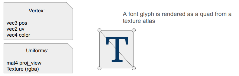
I was most recently working on some basic shaders for the game. I had just added font rendering with its own shader for rendering glyph quads. A UI system typically needs things beyond just font glyphs, like UI panels and sprite icons, and those are mostly just basic quads as well. It seemed obvious that I could share a shader for the dual uses of rendering font quads and rendering sprite quads:
The shader is really simple. In the vertex shader, the position is just:
gl_Position = proj_view * vec4(aPosWorld, 1.0);And then the fragment shader uses the input color as a componentwise multiplier after looking up the texture value via the UV coordinate:
vec4 tex_color = texture(u_texture, uv);
FragColor = color * texture_rgba;
The font atlas has white glyphs, which means this color multiplier produces fonts that look like we want. Colored sprites are typically rendered with color = [1,1,1,1] so that we don’t affect them, but you can also tint them by changing up the values.
Rendering quads is also straightforward, but when you’re doing it all yourself, there is still a fair amount of stuff to keep track of. Every glyph in the font has a packed quad that tells us its size and its UV coordinates in the font atlas. We write the quad vertices into a VBO, and rather than writing six vertices to get the two triangles per quad, we only write the four unique ones and use an EBO to define the quads by indexing into the vertex array (as is standard practice):
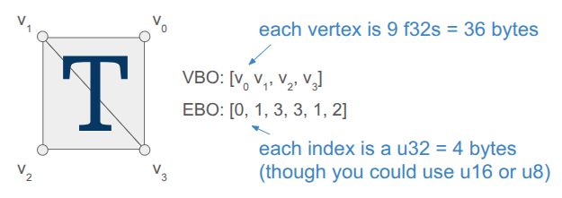
Each frame, the backend fills up a vertex buffer and sends it to the VBO for rendering. This only needs to happen once, if the sprites and the font glyphs are all packed into the same texture and everything uses the same projection and view matrix.
Render Commands
The core game code does not directly fill the vertex buffer. Instead the core game code issues more simple render commands. These commands are simple, higher-level descriptions of what we want rendered, making the core game code fast and separating out the task of deciding how to render everything up to the backend.
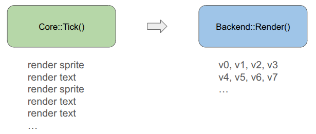
For example, a render text command is:
struct RenderCommandTextLine {
    FontHandle font_handle;
    glm::vec2 pos;       // Bottom-left of the first glyph
    f32 letter_size;     // Multiplier off of default
    f32 letter_spacing;  // Multiplier off of default
    s8 text;             // Must last until rendered
    glm::vec4 color;     // RGBA componentwise color multipliers
};
It is up to the backend to convert that higher-level specification into the actual quad vertices, moving that non-trivial logic out of the core game loop and into its own location. The render command thus acts as an API between the game and the backend. Any new backend that we support in the future must be able to render these things.
In the future, when I might have partially transparent objects, the backend can do more sophisticated things like render all opaque geometry first and then sort the transparent objects by depth and render them in a second pass. Something like that is very hard to do when the core logic is rendering as it goes.
Including Triangles
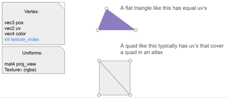
So far, we have a shader that can render both font glyphs and sprites. That’s nice, but I want Into Depth to have a low-poly, flat-color aesthetic. I wanted to add UI panels that underlay the text, and I want those to be tessellated:

A panel like that is comprised of a relatively small number of triangles when compared to a modern 3D character mesh (~40 vs. 1000’s). It should be cheap enough for us to directly write that geometry out every frame.
Our font + sprite shader can actually be used to draw basic triangles, we just need to point all three vertices of the triangle to all-white uv coordinates so that we get the color we want. This is achieved by including a \(1 \times 1\) .
I thus define some additional render commands, such as RenderCommandPanel, that act as high-level descriptions of what should be rendered, and then have the backend construct the mesh live in the vertex buffer and send it over. Doing this does not use the quad-specific EBO, so for now I’m just using a glDrawArrays call instead of a glDrawElements call.
I did make one adjustment to the shader – rather than switching out the textures depending on my use, I just have an array of textures that I can leave bound and have each vertex declare which one its UV coordinate applies to:
I pack my fonts into a font atlas that is uploaded as the first texture, then have a series of sprite atlases.
Sprite Packing
I need to bake my font glyphs and my sprites into a series of textures that my shader can then use. There are plenty of tools that do sprite packing for you. I was already using stb_truetype and stb_rect_pack to create my font atlas, so I decided to write my own sprite packer on top of stb_rect_pack.
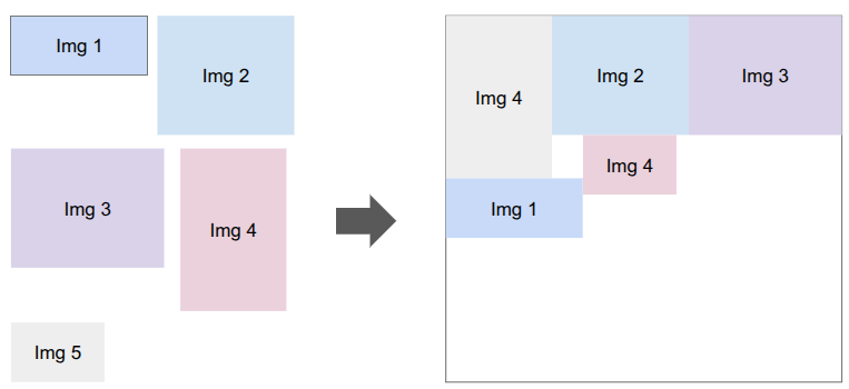
Conceptually, it is really simple. I give it a set of individual sprites, and it keeps trying to pack as many as possible into a new texture until everything is packed. The only little gotcha is that a \(w \times h\) sprite is packed as a \(w+2 \times h+2\) rectangle in order for it to be padded with a 1-pixel extended border to fight edge bleeding caused by inaccuracies in UV coordinates between mipmap levels.
Shader Code Organization
Beyond assets, shaders themselves tend to more complexity than you’d think because the code to use them ends up spread all over the codebase. The vertex and fragment shader definitions are often two separate .glsl files, which live in their own folder alongside the other shaders. The C++ side typically needs a vertex struct defined somewhere, and then we need both CPU-side vertex buffers and references to the GPU-side shader program IDs, VAO, VBO, and EBOs. Whenever we use a shader, we need to activate it, which involves more code that has to use these references and set various shader uniforms.
I’ve adopted a few enhancements to reduce the degree of code spread.
The first thing I did was unify the vertex and fragment shaders into a single .glsl file. Since we just read in the file and upload it to the GPU before calling glCompileShader, we can actually process out the necessary portions ourselves. Writing both shaders in the same file helps keep their interdependencies consistent.
#version 330 core

#ifdef VERTEX_SHADER

layout (location = 0) in vec3 aPosWorld;
layout (location = 1) in vec4 aVertexColor; // rgba
layout (location = 2) in vec2 aTexCoords;

out vec4 vertex_color;
out vec2 tex_coords;

uniform mat4 model;
uniform mat4 view;
uniform mat4 projection;

void main()
{
   gl_Position = projection * view * model * vec4(aPosWorld, 1.0);
   vertex_color = aVertexColor;
   tex_coords = aTexCoords;
}

#endif

//////////////////////////////////////////////////////////////////////////

#ifdef FRAGMENT_SHADER

in vec4 vertex_color;
in vec2 tex_coords;

out vec4 FragColor;

uniform sampler2D atlas;

void main()
{
    float atlas_value = texture(atlas, tex_coords).r;
    FragColor = vec4(vertex_color.rgb, vertex_color.a * atlas_value);
}

#endif
This was nice, but I actually ended up further simplifying by having a single .h file that defines the shader data relevant to the CPU side. The vertex and fragment shaders are still defined in one place, but as explicit strings, and we additionally define a vertex layout:
#pragma once

#include "util/strings.h"
#include "util/vertex_layout.h"

constexpr int kNumUnlitTriangleShaderTextures = 8;

// The vertex data structure (CPU-side)
struct UnlitTriangleVertex {
    glm::vec3 pos;
    glm::vec4 rgba;
    glm::vec2 uv;
    int texture_index;
};

// The shader definition
struct UnlitTriangleShaderDefinition {
    static constexpr const char* kName = "UnlitTriangle";

    static constexpr VertexElement kVertexElements[4] = {
        {ShaderDataType::Vec3F, "aPosWorld", false, offsetof(UnlitTriangleVertex, pos          )},
        {ShaderDataType::Vec4F, "aRGBA",     false, offsetof(UnlitTriangleVertex, rgba         )},
        {ShaderDataType::Vec2F, "aUV",       false, offsetof(UnlitTriangleVertex, uv           )},
        {ShaderDataType::I32,   "aTexIndex", false, offsetof(UnlitTriangleVertex, texture_index)},
    };

    static constexpr VertexLayout kVertexLayout = {
        kVertexElements,
        sizeof(kVertexElements) / sizeof(kVertexElements[0]),
        sizeof(UnlitTriangleVertex)
    };

    static constexpr const char* kVertexShaderSource = R"(
        #version 330 core

        layout (location = 0) in vec3 aPosWorld;
        layout (location = 1) in vec4 aRGBA;
        layout (location = 2) in vec2 aUV;
        layout (location = 3) in int  aTexIndex;

             out vec4 rgba;
             out vec2 uv;
        flat out int  texture_index; // 'flat' means do not interpolate

        uniform mat4 proj_view; // proj * view

        void main()
        {
            gl_Position = proj_view * vec4(aPosWorld, 1.0);
            rgba = aRGBA;
            uv = aUV;
            texture_index = aTexIndex;
        }
    )";

    static constexpr const char* kFragmentShaderSource = R"(
        #version 330 core

             in vec4 rgba;
             in vec2 uv;
        flat in int  texture_index;

        out vec4 FragColor;

        uniform sampler2D textures[8];

        void main()
        {
            vec4 texture_rgba;

            // The 'switch trick' is faster/safer on some drivers.
            switch(texture_index) {
                case 0:  texture_rgba = texture(textures[0], uv); break;
                case 1:  texture_rgba = texture(textures[1], uv); break;
                case 2:  texture_rgba = texture(textures[2], uv); break;
                case 3:  texture_rgba = texture(textures[3], uv); break;
                case 4:  texture_rgba = texture(textures[4], uv); break;
                case 5:  texture_rgba = texture(textures[5], uv); break;
                case 6:  texture_rgba = texture(textures[6], uv); break;
                case 7:  texture_rgba = texture(textures[7], uv); break;
                default: texture_rgba = vec4(1.0,0.0,1.0,1.0); break; // magenta
            }

            FragColor = rgba * texture_rgba;
        }
    )";
};
The vertex layout is just a programmatic representation of the inputs to the Vertex shader. This avoids having to have VBO-creation code that lives elsewhere depend on this shader. We can go from code like this:
// vertex positions
u8 attribute_index = 0;
glEnableVertexAttribArray(attribute_index);
glVertexAttribPointer(attribute_index++, 3, GL_FLOAT, GL_FALSE, sizeof(Vertex),
                      (void*)offsetof(Vertex, position));
// vertex normals
glEnableVertexAttribArray(attribute_index);
glVertexAttribPointer(attribute_index++, 3, GL_FLOAT, GL_FALSE, sizeof(Vertex),
                      (void*)offsetof(Vertex, normal));
// uv coordinates
glEnableVertexAttribArray(attribute_index);
glVertexAttribPointer(attribute_index++, 2, GL_FLOAT, GL_FALSE, sizeof(Vertex),
                      (void*)offsetof(Vertex, uv));
// bone ids (max 4)
glEnableVertexAttribArray(attribute_index);
glVertexAttribIPointer(attribute_index++, 4, GL_INT, sizeof(Vertex),
                       (void*)offsetof(Vertex, bone_ids));
// bone weights (max 4)
glEnableVertexAttribArray(attribute_index);
glVertexAttribPointer(attribute_index++, 4, GL_FLOAT, GL_FALSE, sizeof(Vertex),
                      (void*)offsetof(Vertex, bone_weights));
to just running:
for (u32 i = 0; i < vertex_layout.n_elements; i++) {
    SetUpVertexAttrib(i, vertex_layout.elements[i], vertex_layout.stride);
}
where SetUpVertexAttrib looks at the element type and executes the appropriate logic.
void SetUpVertexAttrib(const u8 attribute_index, const VertexElement& element, const size_t stride) {
    glEnableVertexAttribArray(attribute_index);

    switch (element.type) {
    case (ShaderDataType::F32):
        glVertexAttribPointer(attribute_index, 1, GL_FLOAT, GL_FALSE, stride, (void*)element.offset);
        break;

    case (ShaderDataType::Vec2F):
        glVertexAttribPointer(attribute_index, 2, GL_FLOAT, GL_FALSE, stride, (void*)element.offset);
        break;

    case (ShaderDataType::Vec3F):
        glVertexAttribPointer(attribute_index, 3, GL_FLOAT, GL_FALSE, stride, (void*)element.offset);
        break;

    case (ShaderDataType::Vec4F):
        glVertexAttribPointer(attribute_index, 4, GL_FLOAT, GL_FALSE, stride, (void*)element.offset);
        break;

    case (ShaderDataType::I32):
        glVertexAttribIPointer(attribute_index, 1, GL_INT, stride, (void*)element.offset);
        break;
    }
}
My OpenGL backend has the general SetUpVertexAttrib, but it doesn’t have to change if we change the shader. The backend additionally has structs for the GPU object references, the shader uniforms, and their locations:
struct UnlitTriangleShaderRefs {
    GLuint shader_program_id;

    GLuint vao; // vertex array object
    GLuint vbo; // vertex buffer object
    size_t vbo_tri_capacity;  // Number of triangles we have space for in the VBO.

    GLuint ebo_quads; // prepopulated with quad indices
};

struct UnlitTriangleShaderUniforms {
    GLint uniformloc_proj_view; // proj * view from glGetUniformLocation
    GLint uniformloc_textures;

    GLuint texture_ids[kNumUnlitTriangleShaderTextures];
};
This organization scheme has, so far, been much nicer to work with.
Conclusion
When you are writing everything yourself, there is a lot to keep track of. Most of my previous attempts at coding a game “from scratch” struggled under mounting complexity. Unifying font, sprite, and basic unlit geometry rendering under one shader helps alleviate that complexity. Even more so, having good separations of concern between the core game logic and the backend lets the game logic just have simple references to assets and focus on the game, and the backend figure out how to fill vertex buffers and ship them to the GPU.
Happy New Year!